


 English
WT9932P4C61-TINY Getting Started Guide
Update history
| Date | Version | Author | Update content |
|---|---|---|---|
| 2026-07-09 | 1.0.0 | Yobie Zhou | Initial documentation update |
1. Tutorial Objectives
This guide is intended for first-time users of the WT9932P4C61-TINY. It walks you through the complete process, from becoming familiar with the board to flashing and verifying the firmware.
The WT9932P4C61-TINY is a dual-chip development board based on the ESP32-P4 + ESP32-C61. Most applications run on the ESP32-P4, while the ESP32-C61 provides wireless connectivity. Pay attention to the purpose of each USB port during development:
| Port | Name Used in This Guide | Main Purpose |
|---|---|---|
| FUSB Type-C | FUSB / Full-Speed USB |
Flash, power, and view logs from the ESP32-P4 |
| HUSB Type-C | HUSB / High-Speed USB |
Supports USB CDC; after the P4 is flashed with bridge firmware, this port is used to flash and debug the ESP32-C61 |
Note: Use
FUSBfor routine flashing ofESP32-P4examples. Switch toHUSBas described in this guide only when you need to flash or debug the onboardESP32-C61separately.
2. Preparation
2.1 Hardware
- One
WT9932P4C61-TINYdevelopment board. - A reliable USB Type-C data cable. Prepare at least one cable that supports data transfer.
- A Windows, Linux, or macOS computer.
- To use all factory test features, the following accessories are recommended:
- A MIPI DSI display with a pinout compatible with the board.
- A MIPI CSI camera with a pinout compatible with the board.
- A MicroSD card.
- An available Wi-Fi network.
The factory test firmware can still start without a display, camera, or SD card. Missing peripherals are indicated by the RGB LED and on-screen status information.
2.2 Software
There are two ways to flash firmware to the WT9932P4C61-TINY:
- Use the Wireless-Tag Online Flashing Tool. No software package needs to be installed in advance. Open the tool in a browser to flash firmware, erase flash, read chip information, monitor the serial port, back up flash contents, verify firmware, and perform other operations.
- Use Espressif's Flash Download Tool. Follow the link to download the tool.
Flashing with the Online Tool
Download the Firmware Packages
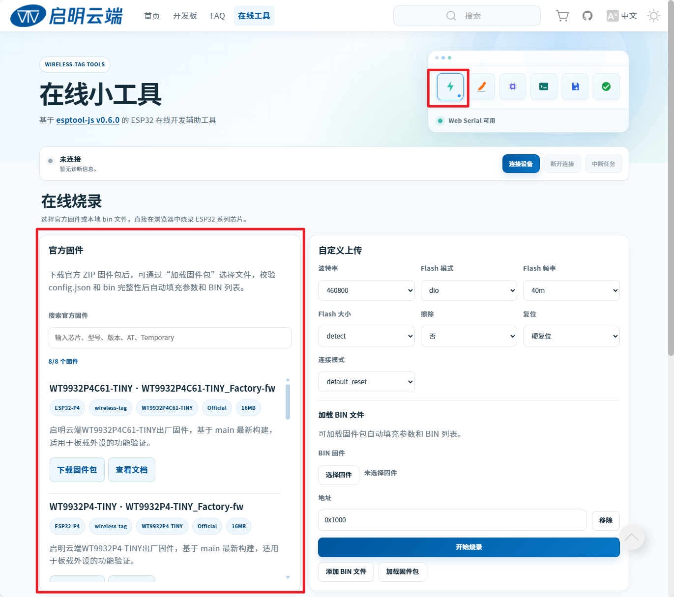
Open the Wireless-Tag Online Tool. The page appears as shown below:

First, download the three required firmware packages. On the page, select Online Flashing > Official Firmware in the area shown below:
Scroll through the highlighted area and select the following three packages. Check each firmware name carefully:
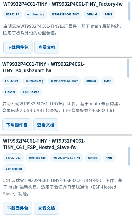
Click Download Firmware Package to download a package. The three downloaded packages are:
Note: Do not extract the downloaded packages. Load the ZIP files directly into the online flashing tool in the following steps.
| Name | Description |
|---|---|
| WT9932P4C61-TINY_P4_USB2UART-fw-20260710-online.zip | Flash this first. It is the transition firmware used to flash the C61. Flash it through the FUSB Type-C port, then disconnect FUSB and connect HUSB to flash the C61 firmware. |
| WT9932P4C61-TINY_C61_ESP-HOSTED-SLAVE-fw-20260710-online.zip | Flash this second after completing the preceding step. |
| WT9932P4C61-TINY_Factory-fw-20260709-online.zip | Flash this third, after the first two firmware packages have been flashed. |
After downloading all three ZIP packages, continue with the following flashing steps.
Flashing Steps
Flashing sequence:
Connect FUSB and flash the first firmware package.
Connect HUSB, restart the flashing tool, select ESP32-C61, and flash the second firmware package.
Connect FUSB, restart the flashing tool, select ESP32-P4, and flash the third firmware package.
Flash the first package (
WT9932P4C61-TINY_P4_USB2UART-fw-20260710-online.zip). Connect the Type-C end of a USB cable to theFUSBport and the other end to the computer. Open the online tool, then clickConnect Deviceas shown below.A dialog appears after you click
Connect Device. The list may contain multiple devices. If you cannot identify the board's COM port, disconnect the other devices or unplug and reconnect this board to determine which COM port belongs to it.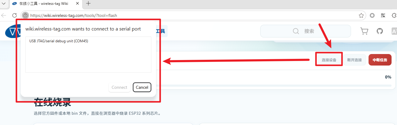
Select the device's COM port and click
Connect. Check the log area at the bottom of the page for the connection status. A successful connection is shown below: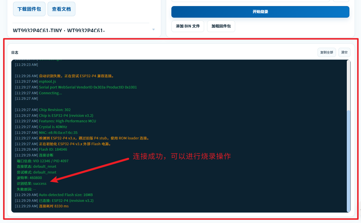
After the connection succeeds, click
Load Firmware Package. In the file dialog, select the first package, WT9932P4C61-TINY_P4_USB2UART-fw-20260710-online.zip: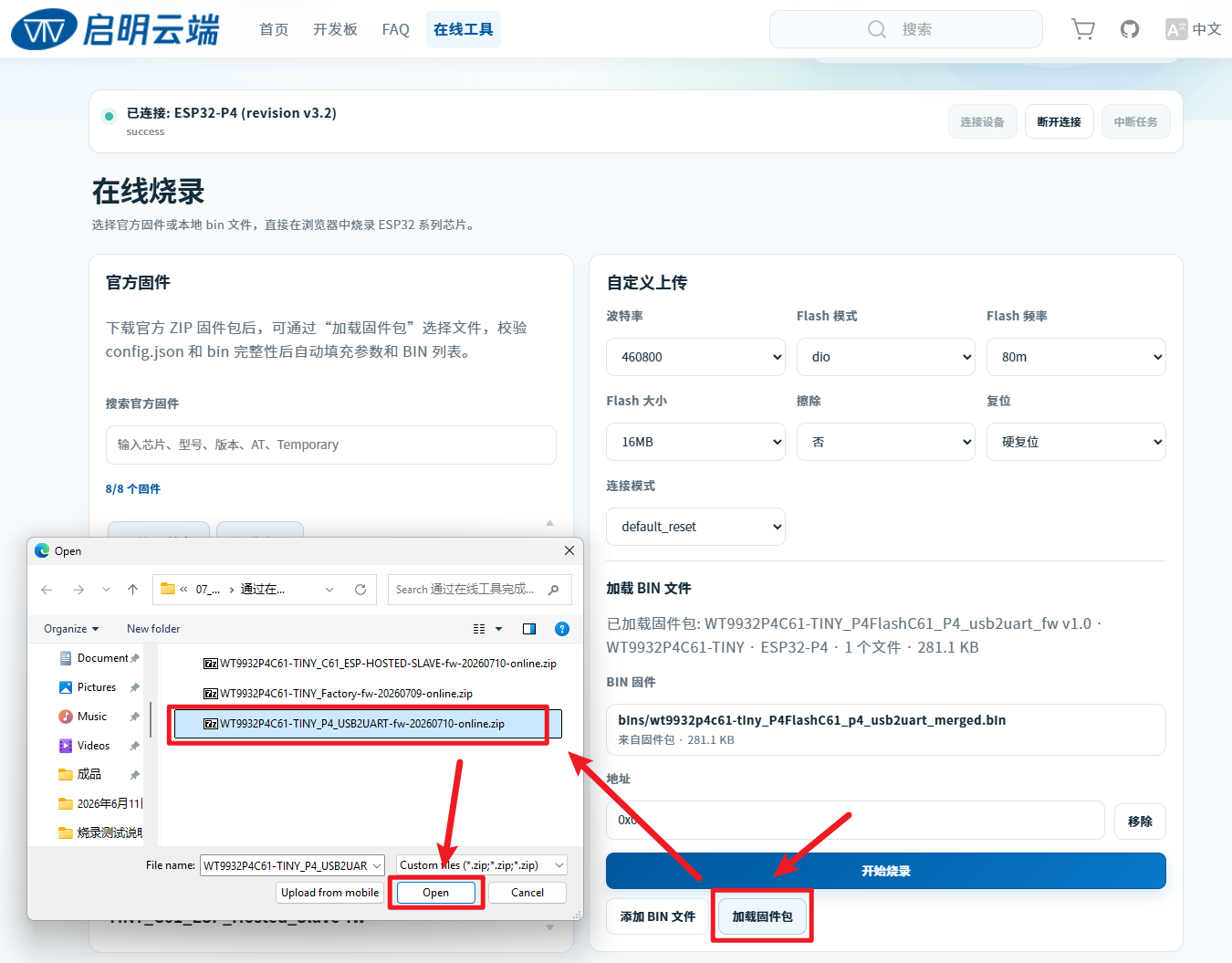
Click
Start Flashing. A confirmation dialog appears at the top of the page; clickOKto begin flashing: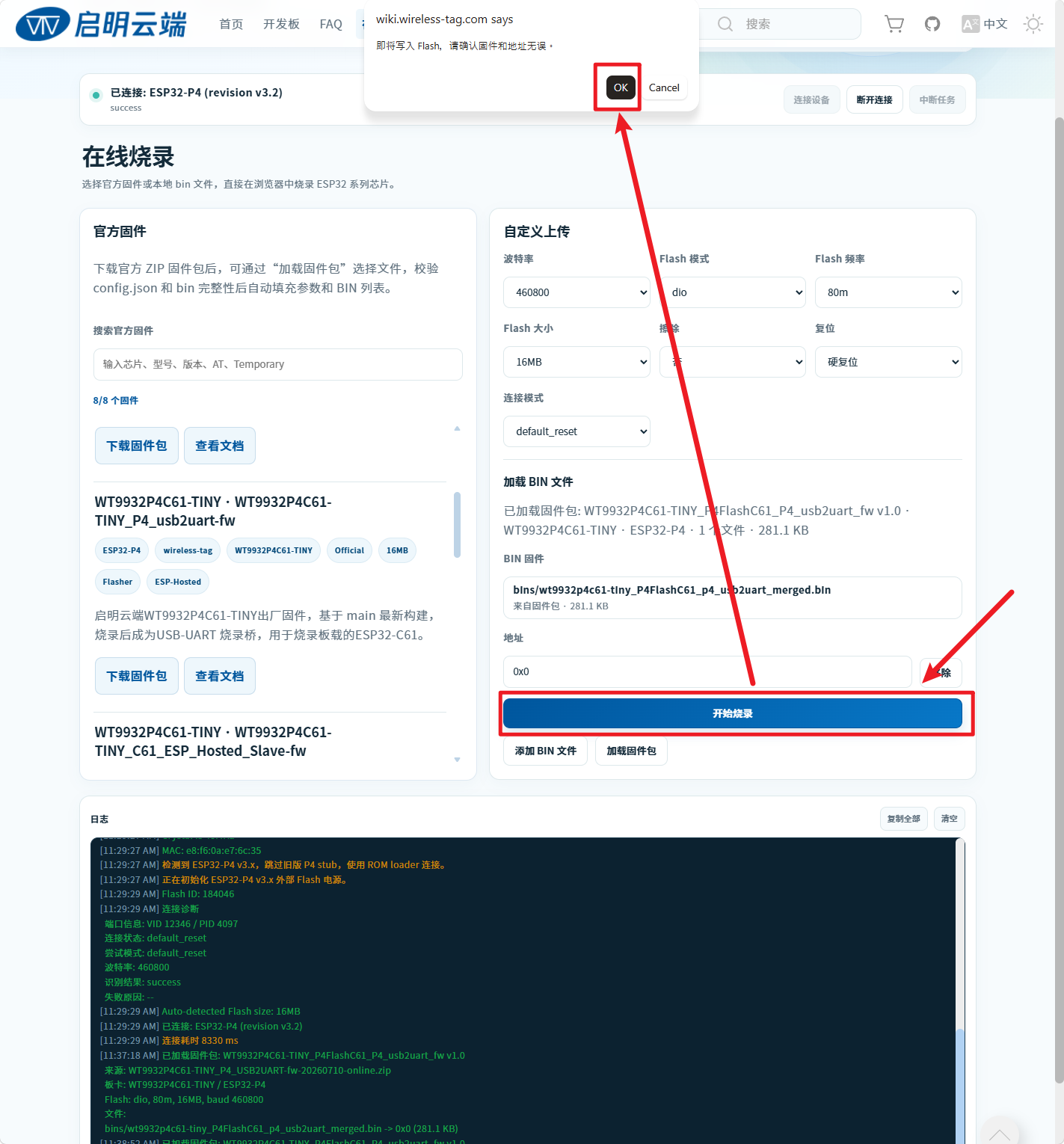
The following message indicates that flashing is complete:
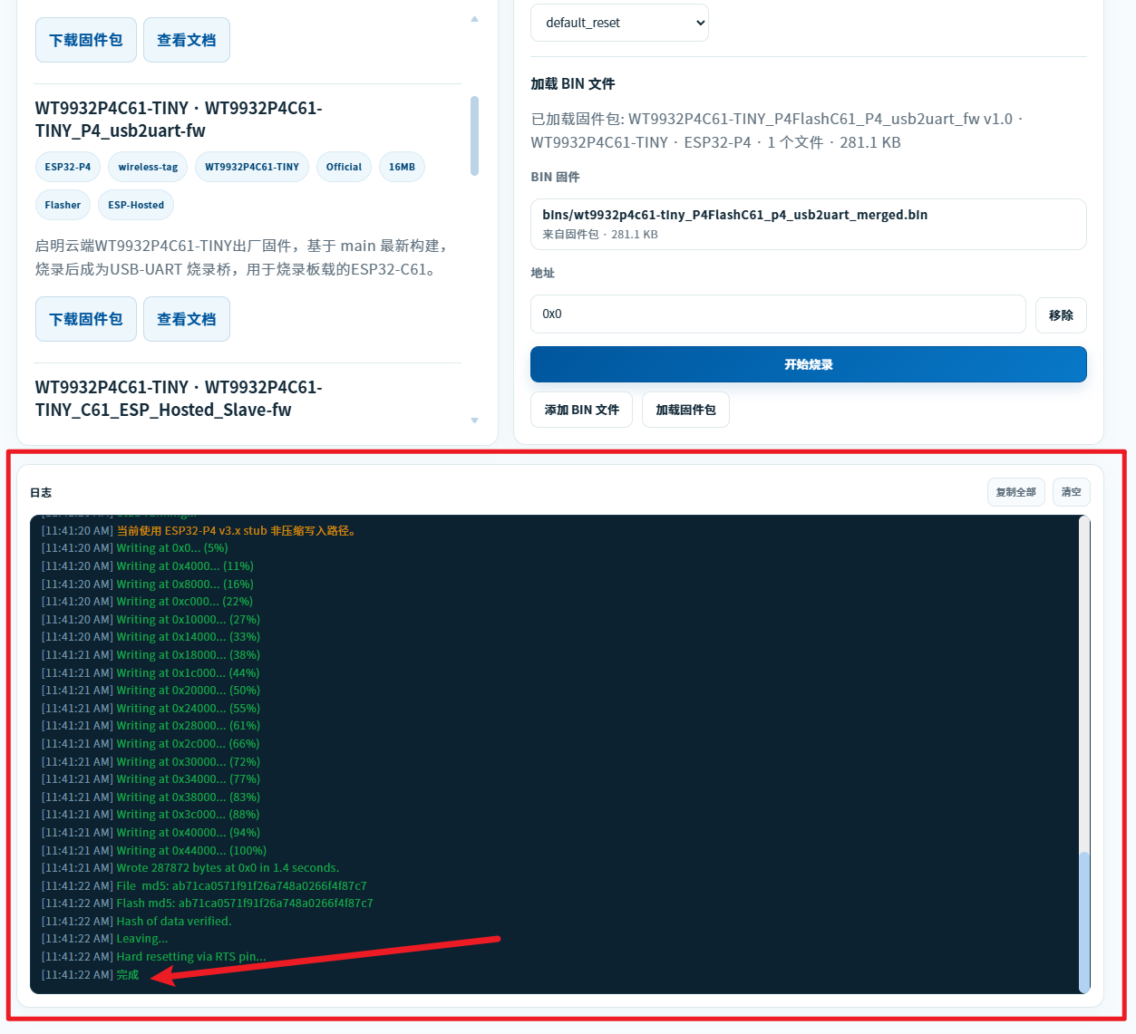
The first firmware package has now been flashed. Disconnect the Type-C cable from the board before proceeding to the next package.
Flash the second package (
WT9932P4C61-TINY_C61_ESP-HOSTED-SLAVE-fw-20260710-online.zip). Connect the Type-C end of the USB cable to theHUSBport (make sure you use HUSB) and the other end to the computer. ClickConnect Deviceand select the device's COM port in the dialog. Check the connection status in the log area. The messages may differ from the first connection, but a final success message indicates that the connection succeeded: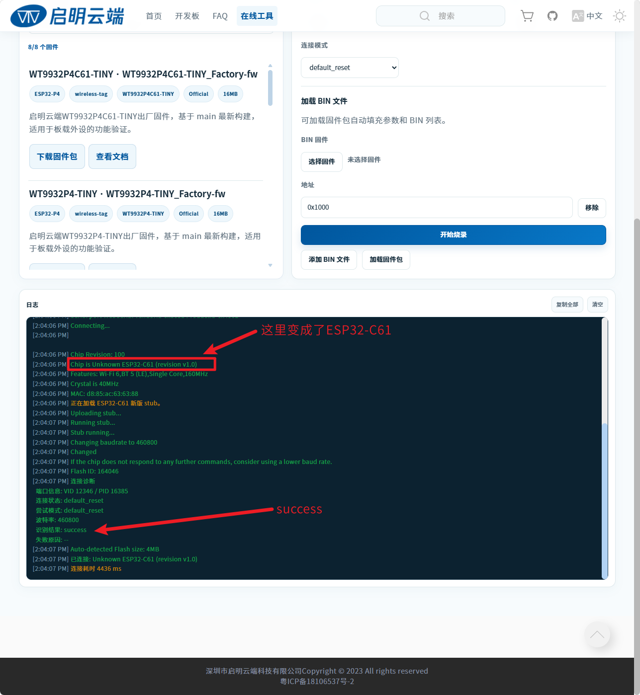
After the connection succeeds, click
Load Firmware Package. In the file dialog, select the second package, WT9932P4C61-TINY_C61_ESP-HOSTED-SLAVE-fw-20260710-online.zip: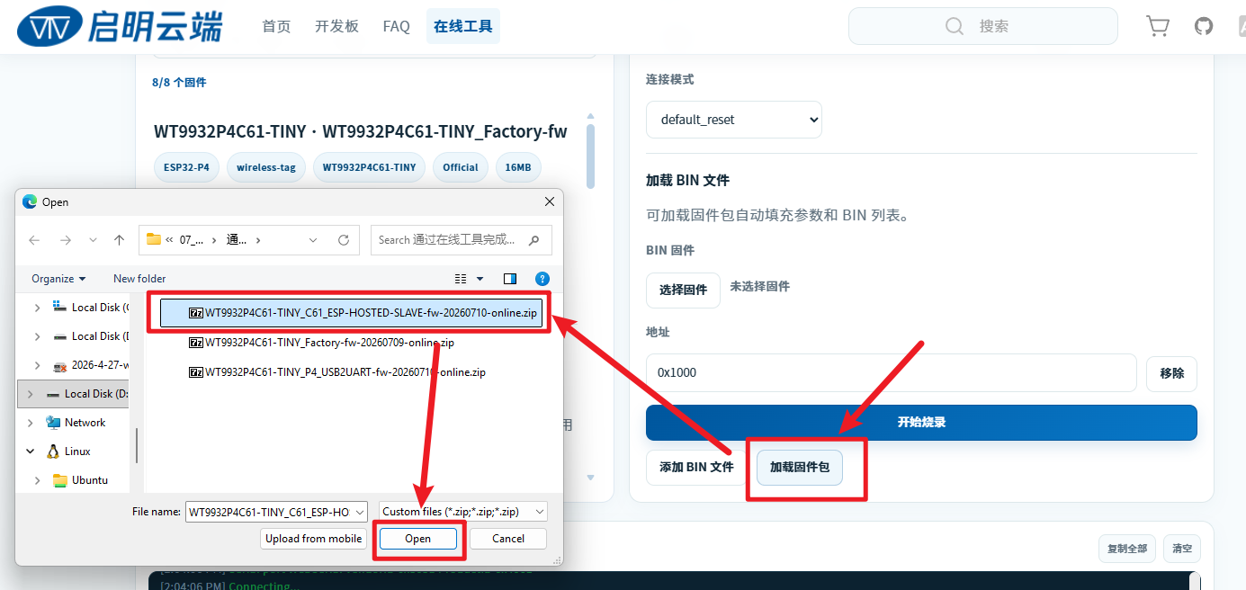
Click
Start Flashing. When the confirmation dialog appears at the top of the page, clickOKto begin flashing: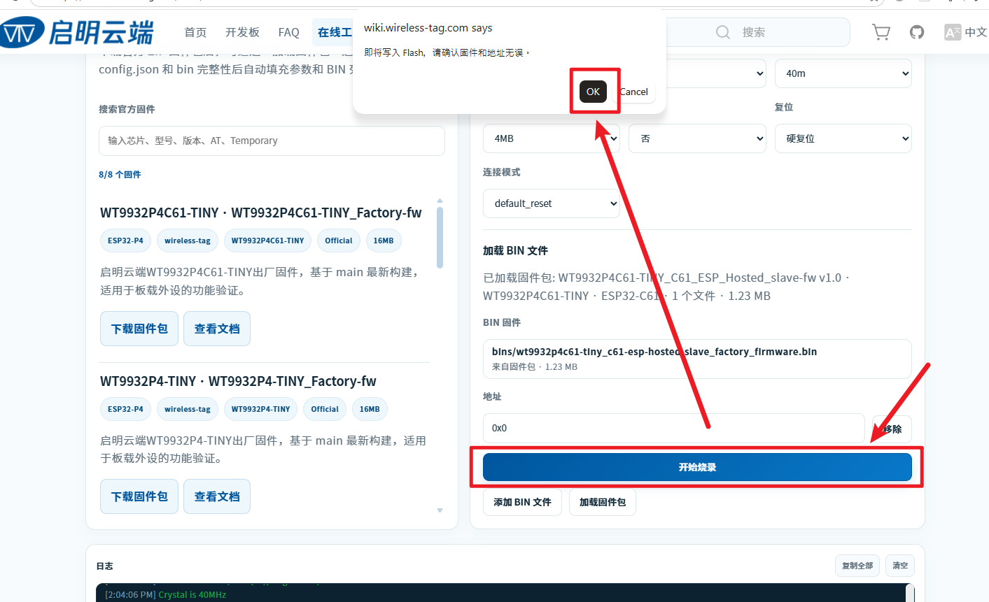
The following message indicates that flashing is complete:
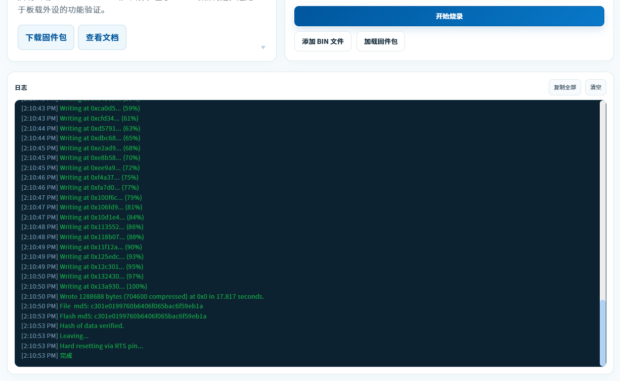
The second firmware package has now been flashed. Disconnect the Type-C cable from the board before proceeding to the final package.
Flash the third package (
WT9932P4C61-TINY_Factory-fw-20260709-online.zip). Connect the Type-C end of the USB cable to theFUSBport (make sure you use FUSB) and the other end to the computer. ClickConnect Deviceand select the device's COM port in the dialog. Check the connection status in the log area.After the connection succeeds, click
Load Firmware Package. In the file dialog, select the third package, WT9932P4C61-TINY_Factory-fw-20260709-online.zip: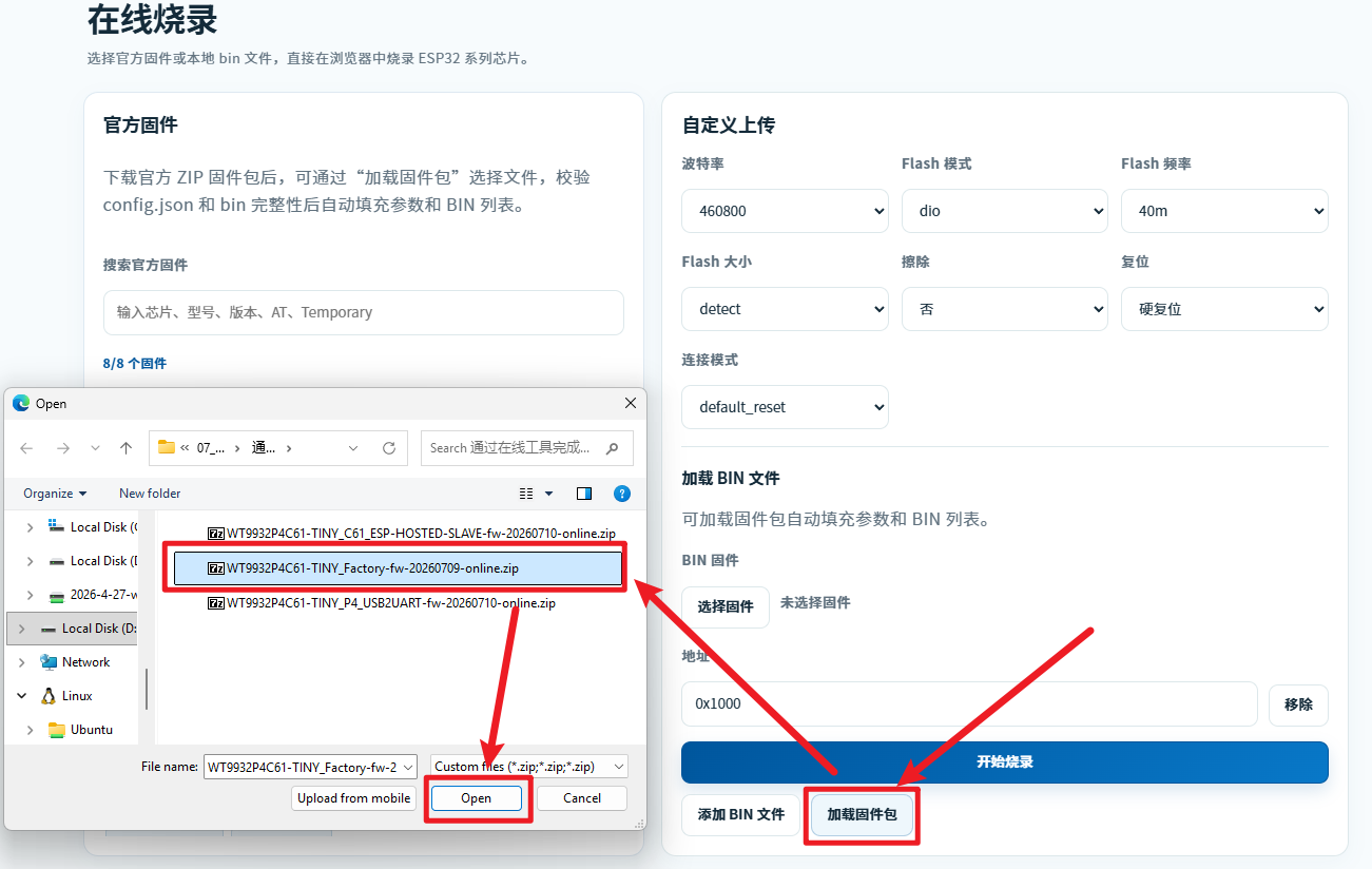
Click
Start Flashing. When the confirmation dialog appears at the top of the page, clickOKto begin flashing. The following message indicates that the final package has been flashed successfully: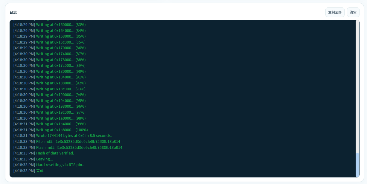
All three firmware packages have now been flashed. Disconnect the Type-C cable from the board, then proceed to the test and verification steps.
Flashing with Flash Download Tool
Click here to download the resource package required for flashing. The Flash Download Tool is included in the package.
File Descriptions
| Name | Description |
|---|---|
| 01_P4C61第1个烧录的固件-通过FUSB烧录.bin | Flash this first. It is the transition firmware used to flash the C61. Flash it through the FUSB Type-C port, then disconnect FUSB and connect HUSB to flash the C61 firmware. |
| 02_P4C61第2个烧录的固件-通过HUS烧录.bin | Flash this second after completing the preceding step. |
| 03_P4C61第3个烧录的固件-通过FUSB烧录.bin | Flash this third, after the first two firmware files have been flashed. |
| flash_download_tool.zip | The flashing tool used to flash the three firmware files listed above. |
Flashing Steps
Flashing sequence:
Connect FUSB and flash the first firmware file.
Connect HUSB, restart the flashing tool, select ESP32-C61, and flash the second firmware file.
Connect FUSB, restart the flashing tool, select ESP32-P4, and flash the third firmware file.
Prepare the flashing tool. No installation is required. Extract
flash_download_tool.zip, then double-click the executable as shown below: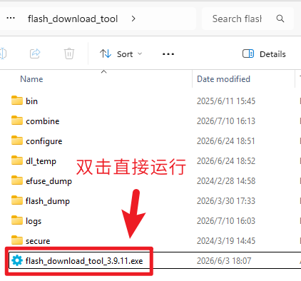
Two windows open when you run
flash_download_tool_3.9.11.exe. Ignore the black console window and make the selection shown below in the other window: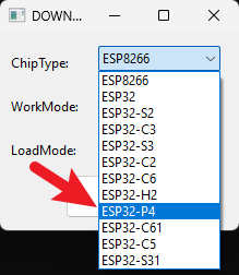
After selecting
ESP32-P4, the following page appears, indicating thatflash_download_tool_3.9.11.exeis running correctly: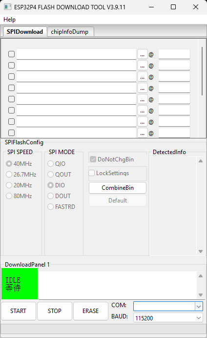
Connect the Type-C end of a USB cable to the
FUSBport and the other end to the computer. Inflash_download_tool, select01_P4C61第1个烧录的固件-通过FUSB烧录.binand configure the options as shown below:Configuration notes:
Select the checkbox marked ①.
Click the
...button marked ② to browse for the firmware file.Enter
0x0in the field marked ③.Click the control marked ④ to open the device list marked ⑤. If the list contains multiple devices, disconnect the other devices or unplug and reconnect this board to identify the correct COM port.
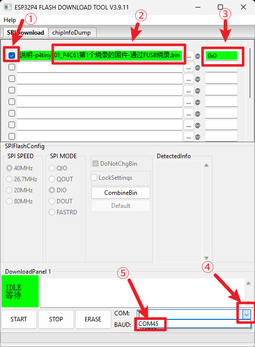
Flash the first firmware file,
01_P4C61第1个烧录的固件-通过FUSB烧录.bin. After confirming the settings above, select a baud rate of460800. If flashing fails, reduce the baud rate to115200. ClickSTARTto begin. Flashing in progress is shown below: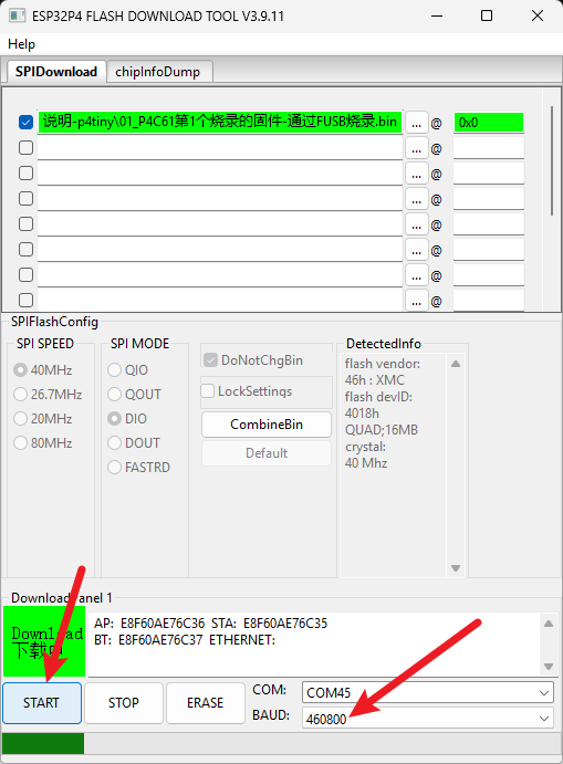
When flashing is complete, close
flash_download_tool(the tool must be closed before continuing).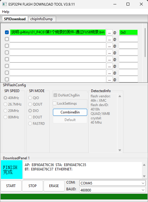
Flash the second firmware file,
02_P4C61第2个烧录的固件-通过HUS烧录.bin. After completing the preceding step, disconnectFUSBand connect the Type-C cable toHUSB. Openflash_download_tooland selectESP32-C61at startup: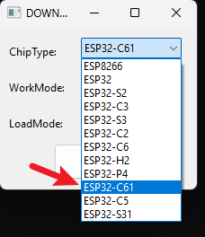
Configure the tool as in the preceding steps, select
02_P4C61第2个烧录的固件-通过HUS烧录.bin, and start flashing as shown below: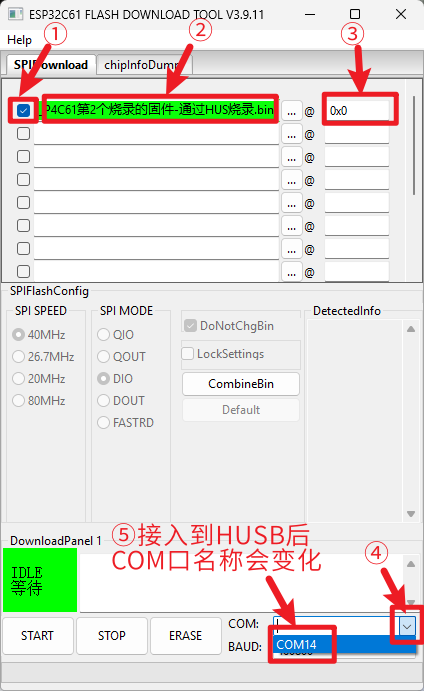
Click
STARTand wait for flashing to complete: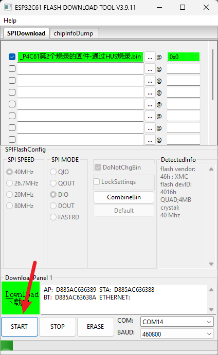
When flashing is complete, close
flash_download_tool(the tool must be closed before continuing).Flash the third firmware file,
03_P4C61第3个烧录的固件-通过FUSB烧录.bin. After completing the preceding step, disconnectHUSBand reconnect the Type-C cable toFUSB. Openflash_download_tooland selectESP32-P4at startup:The previously selected firmware remains in the list. Clear its checkbox, add the new firmware file, and select its checkbox as shown below:
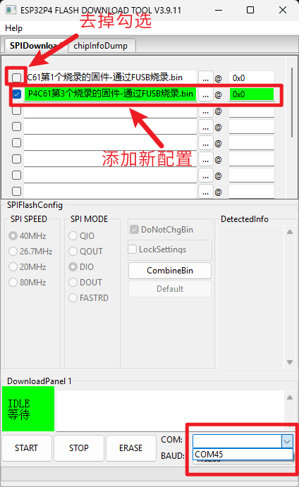
Wait for flashing to complete. You do not need to close
flash_download_tool; the hardware kit is now ready for testing.Flashing sequence:
Connect FUSB and flash the first firmware file.
Connect HUSB, restart the flashing tool, select ESP32-C61, and flash the second firmware file.
Connect FUSB, restart the flashing tool, select ESP32-P4, and flash the third firmware file.
Test Procedure
After flashing all three firmware files as described above, disconnect the Type-C cable from the board.
Basic Test
Use the basic test if you do not have a display, camera, or SD card.
Connect a Type-C cable to power the board. If the red LED turns on within three seconds, the program is running normally and the basic test has passed.
Full Test
Prepare all hardware shown below. Items enclosed together in a red box form a matching pair:
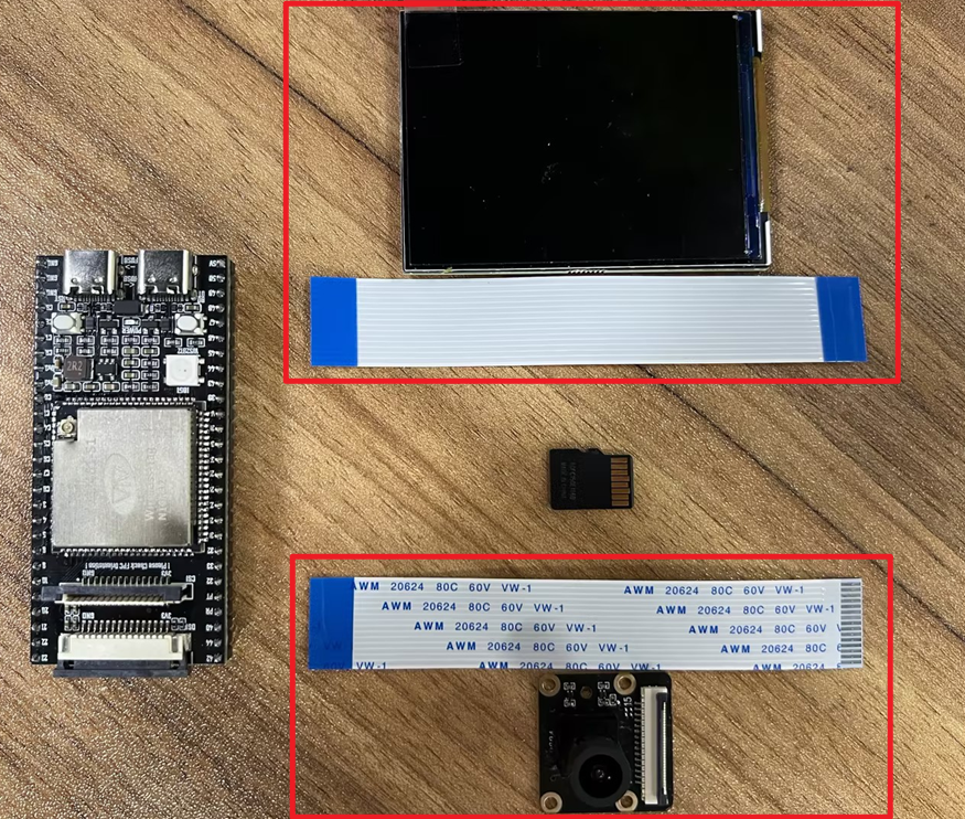
Connect the hardware as shown below. The SD card is already inserted into the slot on the back of the board and is therefore not shown separately.
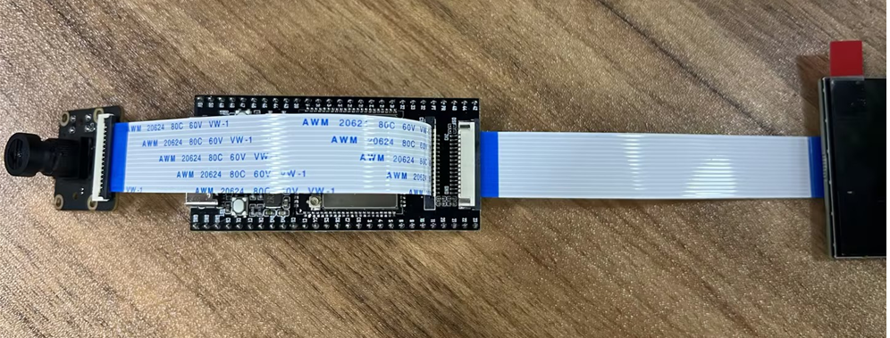
Connect either Type-C port to power the board.
Normal operation is indicated by the following:
- The RGB LED is purple.
- The camera image appears on the display.
- The touchscreen responds to input: drag the slider to change the RGB LED color, tap the camera area to enlarge or reduce the preview, and tap
SD Card Mount. The status should display Success. - The box in the lower-right corner displays the green text
AP:WT9932P4C61-xxxx. The four digits represented by xxxx differ between devices because they are derived from the MAC address.
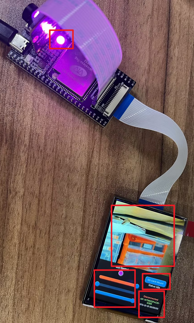
RGB LED Color Meanings
The RGB LED provides important status information. The meaning of each color is shown below:
| LED Color | Status |
|---|---|
| Blue | The camera is disconnected, or Wi-Fi is scanning, connecting, or reconnecting |
| Green | All peripherals are operating normally, or Wi-Fi is connected |
| Yellow | The SD card is disconnected |
| Pink | The display is disconnected |
| Red | All peripherals are disconnected, or Wi-Fi is disconnected or failed to connect |
| Purple | Provisioning mode is active |
10. Next Steps
After completing this guide, continue with the Development Guide in the same directory. It explains how to create a project based on /home/wireless-tag/work/WT_BSP, select a board, call BSP APIs, tailor peripheral capabilities, and extend application functionality.