English
WT32-ETH01 Feature Introduction
2026-05-12
Update history
| Date | Version | Author | Update content |
|---|---|---|---|
| 2026-05-12 | 1.0.1 | Yobie Zhou | Added board images and purchasing links |
| 2025-06-19 | 1.0.0 | Kirto | Initial document release |
1. Introduction
The WT32-ETH01, launched by Wireless-tag, is an embedded development board module based on Espressif's ESP32 series, focusing on simplifying device networking and data communication.
Its core positioning is to provide an efficient and low-cost serial-to-Ethernet solution for Internet of Things (IoT) applications, suitable for various scenarios such as smart homes, industrial automation, and energy monitoring.
Buy Now: WT32-ETH01 Development Kit
1.1 🔧 Core Hardware Configuration
- Main Control Chip: Equipped with the Espressif
ESP32dual-modeSoC, integrating2.4GHz Wi-Fi(supporting802.11 b/g/nprotocol) andBLE 4.2(BR/EDR + BLE), featuring high RF performance and ultra-low power consumption characteristics. - Network Interface: Provides an
RJ45Ethernet port (10/100Mbpsauto-negotiation), supporting direct wired network connection, while retainingWi-Fiwireless access capability, enabling dual-network redundancy. - Multi-Data Ports: Includes four data transmission channels: serial port (
UART),Wi-Fi, Ethernet, and Bluetooth, supporting flexible configuration of data passthrough between ports (e.g., UART ↔ Ethernet) viaATcommands.
1.2 🛠️ Design Features
- Flexible Installation: Compatible with both half-pad direct soldering and through-hole connector hardware designs. Can be directly soldered onto the user's
PCBor used for breadboard prototyping, adapting to different engineering scenarios. - Power Supply Compatibility: Supports
5Vor3.3Vdual voltage input (must choose one), with an average operating current of about80mA, suitable for the low-power requirements of embedded devices. - Development Convenience: Supports
ATfirmware, facilitating quick start and development using the module. - Multiple pins are broken out, allowing for secondary development using
ESP-IDF. - Can be developed using the
ETHlibrary inArduino.
1.3 📡 Main Application Scenarios
- Smart Home Gateway: Connects devices like smart bulbs, sockets, and door locks, synchronizing data to the cloud or
APPviaWi-Fi/Ethernet. - Industrial Monitoring: Embedded in distribution boxes to collect real-time current, voltage, and power parameters, transmitting them to the monitoring center via Ethernet.
- Intelligent Security System: Used for devices like door/window sensors and cameras to enable remote alarms and status notifications.
- Agricultural and Medical IoT: Supports sensor data network monitoring (e.g., temperature, humidity, medical device status).
1.4 ⚙️ Development Advantages
- Integrated Protocol Stack: Built-in optimized
TCP/IPprotocol stack, significantly reducing the complexity of device networking development. ATCommand Control: Provides a richATcommand set (e.g.,AT+PASSCHANNELto set passthrough channel,AT+CIPETH_DEFto configure staticIP/DHCP), simplifying network parameter adjustment and data transmission management.OTAUpgrade: Supports remote firmware updates, offering high maintenance convenience.
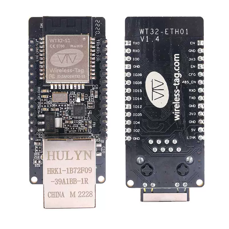
2. Pin Description
2.1 Programming/Debugging Pins
| Name | Function |
|---|---|
| EN | Enable pin, active high |
| GND | Ground pin |
| 3V3 | 3.3V input pin |
| TXD | Serial output pin for programming/debugging |
| RXD | Serial input pin for programming/debugging |
| IO0 | Boot mode pin for programming |
2.2 O Pin Description
| Name | Function |
|---|---|
| EN | Enable pin, active high |
| CFG | IO32 pin, used for hardware factory reset |
| 485_EN | IO33, Enable pin for RS485 |
| RXD | IO5, Input pin for uart2 |
| TXD | IO17, Output pin for uart2 |
| GND | Ground pin |
| 3V3 | 3.3V power input/output |
| GND | Ground pin |
| 5V | 5V power input/output |
| LINK | Network link indicator LED pin |
| GND | Ground pin |
| IO39 | IO39, input only |
| IO36 | IO36, input only |
| IO15 | General Purpose IO 15 |
| IO14 | General Purpose IO 14 |
| IO12 | General Purpose IO 12 |
| IO35 | IO35, input only |
| IO4 | General Purpose IO 4 |
| IO2 | General Purpose IO 2 |
| GND | Ground pin |
!! When powering, you must choose either the
3V3power supply OR the5Vpower supply!!!
3. Power Characteristics
3.1 Supply Voltage
The module's supply voltage can be either 5V or 3V3. You must choose only one.
3.2 Power Supply Modes
Users can freely choose according to their needs:
- Through-hole (soldering pin headers):
- Power supply via Dupont wires.
- Power supply via breadboard connections.
- Half-pad (directly soldered onto the board): Powered by the user's board.