English
WT9932C61-TINY Feature Introduction
Update history
| Date | Version | Author | Update content |
|---|---|---|---|
| 2026-05-12 | 1.0.1 | Yobie Zhou | Added board images and purchasing links |
| 2025-12-05 | 1.0.0 | Kirto | Initial document release |
1. Introduction
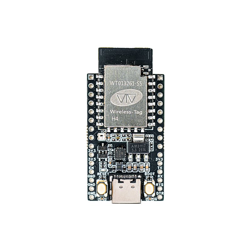
Within the wireless-tag TINY series, WT9932C61-TINY is an ultra-compact Wi-Fi 6 + BLE 5.3 development board based on Espressif’s next-generation ESP32-C61. Continuing the TINY series design philosophy of miniaturization and high integration, it incorporates the module, USB-to-UART, RGB indicator LED, and essential control buttons in a compact 23 × 38 mm footprint—making it an ideal choice for high-performance IoT applications, low-power wireless communication, and rapid prototyping.
ESP32-C61 features a single-core 32-bit RISC-V architecture running up to 160 MHz, supporting Wi-Fi 6 (802.11ax), OFDMA, MU-MIMO, TWT, and enhanced security mechanisms (TEE, PSRAM encryption). Its rich peripheral set (ETM, analog comparator, UART/SPI/I²C/ADC/PWM, etc.) enables it to meet diverse embedded requirements, from smart-home devices to sensor nodes.
As a development board suitable for learning, project validation, and small-scale product integration, WT9932C61-TINY exposes all module GPIOs and can be directly inserted into a breadboard. The onboard CH343P provides plug-and-play USB debugging. Additionally, by shorting EN and GND, the board can switch to USB-TTL mode, making it useful as a multi-purpose debugging tool.
Buy Now: WT9932C61-TINY Development Kit
1.1 🔧 Core Hardware Specifications
- Main Chip: ESP32-C61 (RISC-V single core, 160 MHz)
- Module: WT0132C61-S5
- Wireless: 2.4 GHz Wi-Fi 6 + Bluetooth 5.3 dual-mode
- USB-to-UART: Onboard CH343P
- Buttons: RESET, BOOT (supports download mode)
- LED: 1 × WS2812 RGB LED (IO6)
- Power Design: LDO regulator, up to 1 A output
- Interfaces: Dual-row 15P × 2 (30 pins), all GPIOs exposed
- Connectivity: USB-C, 2.54 mm headers, breadboard-friendly
- Debug Mode: Short EN to GND to switch into USB-TTL tool mode
1.2 🛠️ Design Features
- Compact Size (23 × 38 mm): Ideal for space-constrained applications; onboard USB-to-UART, buttons, and RGB LED enable rapid development out of the box.
- Full GPIO Access, Breadboard-friendly: 2.54 mm pin spacing allows quick sensor experiments and prototyping.
- Dual-purpose Board (USB-to-UART Mode): Short EN and GND to transform the board into a USB-TTL debugger.
- Robust Power Design: Supports up to 1 A, providing stable power for peripherals; onboard power LED displays real-time power status.
- Rich Peripheral Capabilities: ETM, analog comparator, UART/SPI/I²C/PWM/ADC support makes it suitable for complex application scenarios.
1.3 📡 Main Application Scenarios
- Smart Home & Wireless Terminals: Wi-Fi 6 + BLE 5.3 is ideal for lighting control, home sensors, remote controllers, and other devices requiring stable wireless connectivity.
- Education & Maker Projects: Complete GPIO breakout and RGB indicators make it suitable for teaching, experimentation, and rapid prototyping.
- USB-to-UART Debugging Tool: When switched via EN–GND short, it can debug other MCUs or modules, eliminating the need for an additional USB-TTL tool.
1.4 ⚙️ Development Advantages
- USB-C single-cable debugging with onboard CH343P
- Supports ESP-IDF / Arduino / MicroPython ecosystems
- All GPIOs exposed for fast expansion with breadboards
- Wi-Fi 6 + BLE 5.3 for high-performance IoT connectivity
- Onboard RGB LED for demos and status indication
- Can switch to USB-TTL mode to increase hardware utility
- Compact and cost-effective—great for evaluation and pre-production testing
2. Pin Description
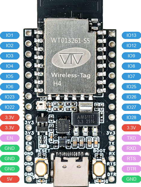
2.1 Left-Side Pins
| No. | Pin | Description | Voltage | Note |
|---|---|---|---|---|
| 1 | IO1 | General-purpose I/O 1 | 0V/3.3V | |
| 2 | IO2 | General-purpose I/O 2 | 0V/3.3V | |
| 3 | IO3 | General-purpose I/O 3 | 0V/3.3V | |
| 4 | IO4 | General-purpose I/O 4 | 0V/3.3V | |
| 5 | IO5 | General-purpose I/O 5 | 0V/3.3V | |
| 6 | IO6 | General-purpose I/O 6 | 0V/3.3V | RGB LED |
| 7 | IO23 | General-purpose I/O 23 | 0V/3.3V | |
| 8 | IO22 | General-purpose I/O 22 | 0V/3.3V | |
| 9 | 3.3V | Power output | 3.3V | |
| 10 | 3.3V | Power output | 3.3V | |
| 11 | EN | Reset pin | 0V | |
| 12 | GND | Ground | 0V | |
| 13 | GND | Ground | 0V | |
| 14 | GND | Ground | 0V | |
| 15 | 5V | Power output | 5V |
2.1 Right-Side Pins
| No. | Pin | Description | Voltage | Note |
|---|---|---|---|---|
| 1 | IO13 | General-purpose I/O 13 | 0V/3.3V | |
| 2 | IO12 | General-purpose I/O 12 | 0V/3.3V | |
| 3 | IO9 | General-purpose I/O 9 | 0V/3.3V | |
| 4 | IO8 | General-purpose I/O 8 | 0V/3.3V | |
| 5 | IO7 | General-purpose I/O 7 | 0V/3.3V | |
| 6 | IO25 | General-purpose I/O 25 | 0V/3.3V | |
| 7 | IO26 | General-purpose I/O 26 | 0V/3.3V | |
| 8 | IO27 | General-purpose I/O 27 | 0V/3.3V | |
| 9 | IO28 | General-purpose I/O 28 | 0V/3.3V | |
| 10 | 3.3V | Power output | 3.3V | |
| 11 | RXD | CH343P UART Receive | 0V/3.3V | |
| 12 | TXD | CH343P UART Transmit | 0V/3.3V | |
| 13 | RTS | CH343P UART Flow Control | 0V/3.3V | |
| 14 | DTR | CH343P UART Flow Control | 0V/3.3V | |
| 15 | GND | Ground | 0V |
3. Power Characteristics
You may power the WT9932C61-TINY development board using any of the following methods:
- Through the
USB Type-Cconnector - By connecting the appropriate voltage to the
VCCpower input using Dupont wires - By connecting the appropriate voltage to the
5Vinput using Dupont wires