English
WT9901C2-SN2 Feature Introduction
2026-05-12
Update history
| Date | Version | Author | Update content |
|---|---|---|---|
| 2026-05-12 | 1.0.1 | Yobie Zhou | Added board images and purchasing links |
| 2025-06-25 | 1.0.0 | Kirto | Initial document release |
1. Introduction
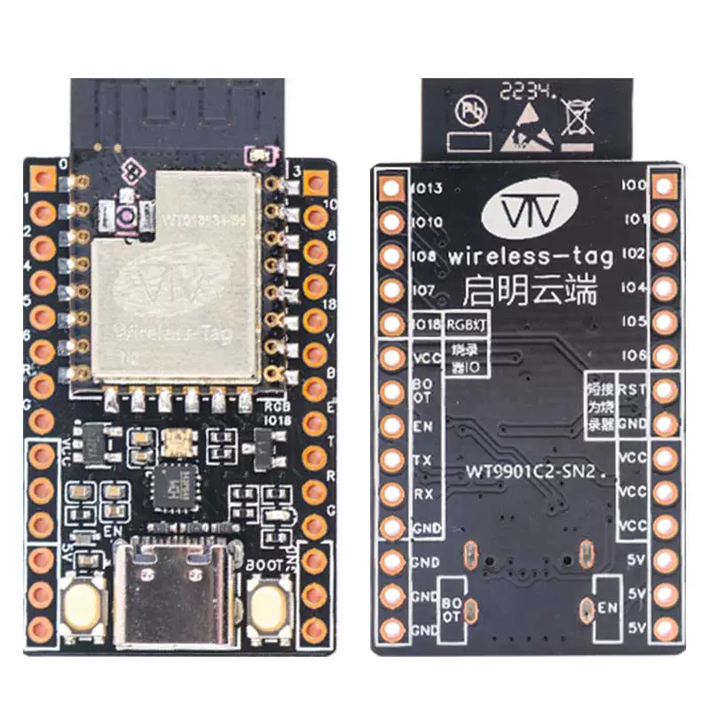
The WT9901C2-SN2 development board, launched by Wireless-tag, is an embedded development board based on the WT018684-S5 module which is designed around Espressif's ESP32-C2. Its core module WT018684-S5 supports dual-mode communication with Wi-Fi and low-power Bluetooth (BLE), uses a PCB onboard antenna, and has built-in 2MB SPI Flash storage, making it suitable for IoT terminal device development.
Additionally, this development board can also function as a simple flasher. It has the same pin sequence as the Wireless-tag flasher ESP-T02.
Buy Now: WT9901C2-SN2 Development Kit
1.1 🔧 Core Hardware Configuration
- Communication Module: Onboard Wireless-tag's self-developed
WT018684-S5module, integratingWi-FiandBLEwireless communication protocols. It features long-range, low-power consumption, and high-connection capacity, suitable for various IoT scenarios. - Pin Expansion: Most of the module's
GPIOsare brought out to pin headers on both sides, facilitating users to connect peripherals via jumpers or directly plug the development board into a breadboard for rapid prototyping and debugging. - Hardware Flexibility: The development board features a compact structure and rich interfaces, suitable for building wireless sensor networks, remote data acquisition, industrial edge nodes, and other application scenarios.
1.2 🛠️ Design Features
- Onboard RGB LED: Onboard
RGBLED for user custom development. - Can Function as Flasher: Can be used as a flasher or serial monitor by connecting
ENandGND. - Breadboard Compatible: Pin spacing supports breadboard development, facilitating users to quickly set up hardware environments.
- High Cost-Effectiveness: Supports both
Wi-FiandBLEat an affordable price.
1.3 📡 Main Application Scenarios
- Smart Home: The module supports
ATcommands and can also be used for secondary development. Suitable for use as aWi-FiorBluetoothmodule in IoT smart home scenarios to assist the main controller in communication for various scenarios. It is a highly cost-effective development board. - Innovative Development and Education: Rich interfaces (I2C/SPI/UART) facilitate connecting peripherals, suitable for
IoTlaboratory prototyping in universities.
1.4 ⚙️ Development Advantages
- Supports development with
ATfirmware, facilitating users to quickly integrateWi-Fiand Bluetooth functionality with their existingMCU. - Supports official
ESP-IDFdevelopment, allowing users to freely control peripherals and customize communication methods. - Supports
Arduinodevelopment, making multi-module development convenient and easy. - Supports
MicroPythondevelopment, lowering the entry barrier as no flashing is required.
2. Pin Description
2.1 Left Pins
| Name | Function |
|---|---|
| IO0 | GPIO0 |
| IO1 | GPIO1 |
| IO2 | GPIO2 |
| IO4 | GPIO4 |
| IO5 | GPIO5 |
| IO6 | GPIO6 |
| RST | Reset pin, used for resetting |
| GND | Power ground |
| VCC | 3.3V power supply |
| VCC | 3.3V power supply |
| VCC | 3.3V power supply |
| 5V | 5V power supply |
| 5V | 5V power supply |
| 5V | 5V power supply |
2.2 Right Pins
| Name | Function |
|---|---|
| IO13 | GPIO13 |
| IO10 | GPIO10 |
| IO8 | GPIO8 |
| IO7 | GPIO7 |
| IO18 | GPIO18 |
| VCC | 3.3V power supply / Output when used as flasher (EN grounded) |
| BOOT | Boot pin for flashing / Output when used as flasher (EN grounded) |
| EN | Reset for flashing / Output when used as flasher (EN grounded) |
| TX | Serial port for flashing / Output when used as flasher (EN grounded) |
| RX | Serial port for flashing / Output when used as flasher (EN grounded) |
| GND | Power ground / Output when used as flasher (EN grounded) |
| GND | Power ground |
| GND | Power ground |
| GND | Power ground |
3. Power Characteristics
You can choose one of the following power supply methods for the WT9901C2-SN2 series development board:
- External power supply via the
USB Type-Cinterface; - Use the
VCCpower input port and connect the corresponding voltage via Dupont wires; - Use the
5Vpower input port and connect the corresponding voltage via Dupont wires;