English
WT9932C3-TINY Feature Introduction
Update history
| Date | Version | Author | Update content |
|---|---|---|---|
| 2026-05-12 | 1.0.1 | Yobie Zhou | Added board images and purchasing links |
| 2025-12-05 | 1.0.0 | Kirto | Initial document release |
1. Introduction
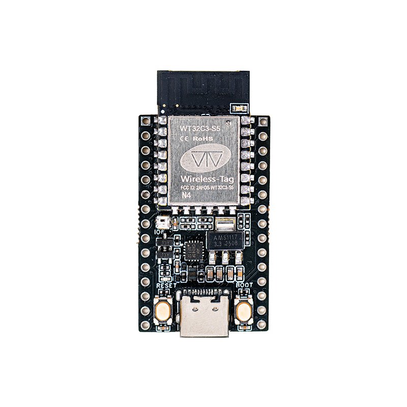
In the wireless-tag TINY series, the WT9932C3-TINY is an ultra-compact Wi-Fi + BLE development board based on the Espressif ESP32-C3. It is designed for entry-level IoT applications, low-power wireless communication, and small-form-factor smart devices.
The ESP32-C3 features a single-core 32-bit RISC-V processor running up to 160 MHz, integrating 2.4 GHz Wi-Fi and Bluetooth LE dual-mode wireless connectivity. It provides common peripheral interfaces such as UART, SPI, I²C, PWM, and ADC, making it suitable for most lightweight embedded projects.
The chip includes a reliable low-power architecture with support for Modem-sleep and Light-sleep modes, as well as secure boot and flash encryption. It is ideal for smart home devices, sensor nodes, wearables, and various IoT products that demand low power and compact size.
As a developer-friendly compact board for the open-source ecosystem, the WT9932C3-TINY integrates USB-to-UART, an RGB indicator LED, reset/BOOT buttons, and fully exposed IO pins. It also supports switching into USB-to-UART mode by shorting EN and GND.
Its design goal is to help developers quickly start with ESP32-C3 at minimal cost while enjoying a complete wireless development experience in a tiny form factor, enabling effortless integration of Wi-Fi/BLE functionality into innovative projects.
Buy Now: WT9932C3-TINY Development Kit
1.1 🔧 Core Hardware Specifications
- Main MCU: ESP32-C3 (single-core RISC-V, up to 160 MHz)
- Module: WT0132C3-S5 (integrates ESP32-C3)
- Wireless: 2.4 GHz Wi-Fi + Bluetooth LE dual-mode
- USB-to-UART: On-board CH343P
- Buttons: RESET, BOOT (supports download mode)
- LED: 1 × WS2812 RGB LED (IO6)
- Power: LDO regulator, up to 1A output
- Interfaces: Dual-row 15P ×2 (30 pins total), full GPIO and system signals exposed
- Connectors: USB-C, 2.54 mm pin headers, breadboard-friendly
- Factory Firmware: MicroPython (boots directly into REPL)
1.2 🛠️ Design Features
- Compact Size (PCB: 23 × 38 mm): Fits space-constrained IoT designs; integrates module, USB-UART, RGB LED, and function buttons for true out-of-box usability.
- Highly Integrated Development Experience: On-board CH343P, no external UART tool required; includes RGB LED, power indicator, RESET/BOOT buttons; all pins exposed for quick prototyping via breadboard.
- Dual-Purpose Board: Can Act as USB-to-UART Tool: When EN and GND are shorted, the board switches to USB-TTL mode to debug other MCUs/modules, greatly improving tool utilization.
- Robust Power Design: LDO regulator with up to 1A output ensures stable performance for peripherals.
- Designed for Scripting Development: Built-in MicroPython allows immediate REPL programming with no flashing required—ideal for learning, experiments, and rapid prototyping.
1.3 📡 Typical Application Scenarios
- Smart Home & Wireless Control Devices: Works as a Wi-Fi/BLE communication node, easily pairing with main MCUs; suitable for smart lighting, door sensors, remote controllers, and other lightweight IoT endpoints.
- Education & Maker Training: Rich IO interfaces (I²C/SPI/UART/ADC) support various sensor expansions; combined with MicroPython, perfect for lab experiments and hands-on teaching.
- USB-to-UART Debugger: Through EN-GND switching, the board can replace an independent USB-TTL module to debug other MCUs or modules.
1.4 ⚙️ Development Advantages
- USB-C for one-cable debugging, easy driver setup
- Built-in MicroPython for zero-threshold learning and validation
- Fully supported by ESP-IDF, Arduino, and MicroPython
- All GPIOs exposed; supports breadboards and perfboards
- Wi-Fi + BLE dual-mode for seamless IoT platform integration
- RGB LED for status indication, demos, and teaching
- USB-TTL mode improves hardware reusability
- Cost-effective and compact; suitable for early-stage prototyping of mass-production projects
2. Pin Description
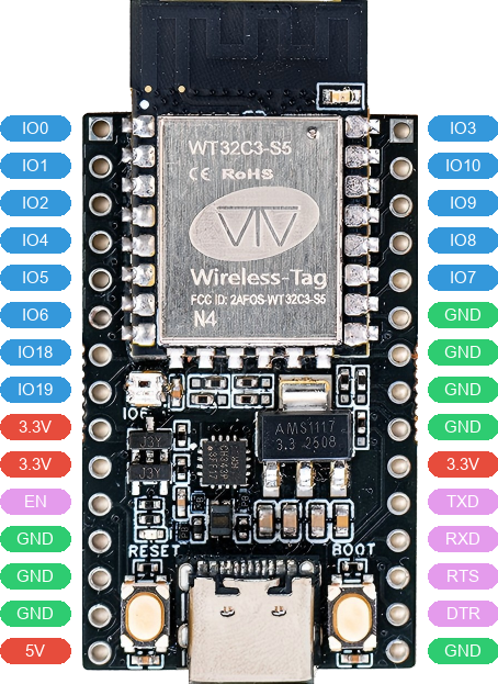
2.1 Left-Side Pins
| No. | Pin | Description | Voltage | Note |
|---|---|---|---|---|
| 1 | IO0 | General-purpose IO 0 | 0V/3.3V | |
| 2 | IO1 | General-purpose IO 1 | 0V/3.3V | |
| 3 | IO2 | General-purpose IO 2 | 0V/3.3V | |
| 4 | IO4 | General-purpose IO 4 | 0V/3.3V | |
| 5 | IO5 | General-purpose IO 5 | 0V/3.3V | |
| 6 | IO6 | General-purpose IO 6 | 0V/3.3V | RGB LED |
| 7 | IO18 | General-purpose IO 18 | 0V/3.3V | |
| 8 | IO19 | General-purpose IO 19 | 0V/3.3V | |
| 9 | 3.3V | Power output | 3.3V | |
| 10 | 3.3V | Power output | 3.3V | |
| 11 | EN | Reset pin | 0V | |
| 12 | GND | Ground | 0V | |
| 13 | GND | Ground | 0V | |
| 14 | GND | Ground | 0V | |
| 15 | 5V | Power output | 5V |
2.2 Right-Side Pins
| No. | Pin | Description | Voltage | Note |
|---|---|---|---|---|
| 1 | IO3 | General-purpose IO 3 | 0V/3.3V | |
| 2 | IO10 | General-purpose IO 10 | 0V/3.3V | |
| 3 | IO9 | General-purpose IO 9 | 0V/3.3V | |
| 4 | IO8 | General-purpose IO 8 | 0V/3.3V | |
| 5 | IO7 | General-purpose IO 7 | 0V/3.3V | |
| 6 | GND | Ground | 0V | |
| 7 | GND | Ground | 0V | |
| 8 | GND | Ground | 0V | |
| 9 | GND | Ground | 0V | |
| 10 | 3.3V | Power output | 3.3V | |
| 11 | RXD | CH343P UART Receive | 0V/3.3V | |
| 12 | TXD | CH343P UART Transmit | 0V/3.3V | |
| 13 | RTS | CH343P UART Flow Control | 0V/3.3V | |
| 14 | DTR | CH343P UART Flow Control | 0V/3.3V | |
| 15 | GND | Ground | 0V |
3. Power Characteristics
The WT9932C3-TINY development board can be powered using any of the following methods:
- Via the
USB Type-Cconnector - By locating the
VCCpower input and connecting the appropriate voltage through Dupont wires - By locating the
5Vpower input and connecting the appropriate voltage through Dupont wires