English
WT99P4C5-S1 Feature Introduction
Update history
| Date | Version | Author | Update content |
|---|---|---|---|
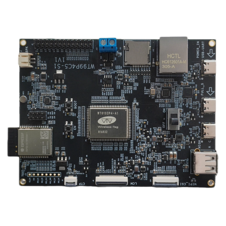
| 2026-05-12 | 1.0.1 | Yobie Zhou | Added board images and purchasing links |
| 2025-06-24 | 1.0.0 | Kirto | Initial document release |
1. Introduction
WT99P4C5-S1 is a high-performance multimedia development board launched by Shenzhen Wireless-tag Co., Ltd., based on the Espressif ESP32-P4 chip (RISC-V dual-core processor, main frequency 400MHz). The core board model is WT0132P4-A1. This development board focuses on full-featured interfaces and multimedia processing capabilities. Application scenarios cover smart home control, industrial HMI, medical equipment, security monitoring, and multimedia terminals, emphasizing low cost, low power consumption, and high integration, suitable for rapid prototyping of products such as IPC and AIoT.
Buy Now: WT99P4C5-S1 Development Kit
1.1 🔧 Core Hardware Configuration
Main Control Chip: Uses Espressif
ESP32-P4+ESP32-C5dual-core heterogeneous architecture, integrating dual-bandWi-Fi 6(802.11ax 2.4/5GHz) andBluetooth 5.0(BR/EDR + BLE) wireless communication, supporting high-throughput data transmission and low-latency IoT interaction. Simultaneously equipped with aRISC-V 400MHzhigh-performance processor, balancing RF stability and edge computing capabilities.Network Interface: Integrated
RJ45Ethernet port (achieving10/100Mbpsauto-negotiation viaIP101GRI PHYchip), supporting high-speed wired network direct connection; simultaneously supports optionalWi-Fi 6dual-band wireless module (2.4/5GHz 802.11ax), achieving wired/wireless dual-stack coordination, ensuring network redundancy and reliable transmission in industrial scenarios.Multi-protocol Data Channels: Natively supports six types of communication ports:
Serial (UART×3),Ethernet,Wi-Fi 6,Bluetooth 5.0,USB 2.0 OTG, andRS-485. Developers can freely implement data routing and protocol conversion between ports (such asUART ↔ Ethernet passthrough) viaESP-IDF SDK, meeting customized industrial control logic requirements.
1.2 🛠️ Design Features
RS-485interface, viaSIT3088EESAtransceiver. Functionality complies withTIA/EIA-485standard, achieving14Mbpsindependent transceiver. Connects to theESP32-P4chip on theWT0132P4-A1core board viaUART. Meets industrial communication requirements.- Onboard
RJ45Ethernet port, connected to theESP32-P4chip on theWT0132P4-A1core board. Meets Ethernet communication requirements. - Full-speed
USB 2.0 Type-Cinterface, can be developed viaESP-IDF. - Onboard power indicator LED and physical switch, convenient for power control.
- High-speed
USB 2.0 Type-C/Type-Ainterface. - Development board supports
4-bitmodeMicroSDcard, can store or play audio files from theMicroSDcard. MIPI CSI FPCconnector (pitch0.5mm, pin count22) for connecting external camera modules, enabling image transmission.MIPI DSI FPCconnector (pitch0.5mm, pin count30) for connectingLCDexpansion boards.- Onboard
ES8311low-power mono audio codec.I2Scommunication. Supports onboard microphone and speaker (maximum support4 Ω3.0W). - The
ESP32-C5on theWT0132P4-A1core board connects to theESP32-P4chip viaSIDO. ProvidesWi-Fi 6capability for the development board.
1.3 📡 Main Application Scenarios
- Industrial Control: Connect to
PLC/sensors viaRS-485interface,Ethernet+Wi-Fi 6dual-redundant networks ensure data transmission reliability. - HMI Human-Machine Interaction: 7-inch
RGBscreen + capacitive touch support for localized monitoring interface development (based on embeddedGUIframeworks likeLVGL). - Security and Visual Processing Terminal:
MIPI-CSI/DVPdual camera interface supports1080P@30fpsimage capture, paired withESP32-P4's400MHz RISC-Vcore for edgeAIinference (e.g., face recognition). - Smart Home Central Control System:
ES8311audio codec supports voice broadcast and local command recognition, combined withHMI Human-Machine Interactionto achieve: smart speaker with screen, home energy management host, etc.
1.4 ⚙️ Development Advantages
- Main control
ESP32-P4can be developed using Espressif SDKESP-IDF. TheESP32-C5can be controlled viaATcommands. - Co-processor
ESP32-C5can be further developed usingESP-IDF. - Official basic function examples provided for easy learning and reference.
2. Pin Description
| Name | Function |
|---|---|
| 3V3 | 3.3 V power supply |
| NC | Empty pin |
| 3v3 | 3.3 V power supply |
| IO0 | GPIO0,LP_GPIO0 |
| 5V | 5 V power supply |
| IO1 | GPIO1,LP_GPIO |
| 5V | 5 V power supply |
| IO2 | GPIO2,MTCK,LP_GPIO2 |
| NC | Empty pin |
| IO4 | GPIO4,MTMS,LP_GPIO4 |
| GND | Power ground |
| IO5 | GPIO5,MTDO,LP_GPIO5 |
| GND | Power ground |
| IO6 | GPIO6,SPI2_HOLD_PAD |
| GND | Power ground |
| IO7 | GPIO7,SPI2_CS_PAD,LP_GPIO7 |
| GND | Power ground |
3. Power Characteristics
You can choose one of the following power supply methods for the WT99P4C5-S1 series development board:
- External power supply via the
Type-Cdebugging interface; - External power supply via the
USB Type-Cinterface; - External power supply via the
USB Type-Ainterface; - Use the
3V3power input port and connect the corresponding voltage via Dupont wires;