


 English
Use WT9932P4-TINY as a UVC Camera
Update history
| Date | Version | Author | Update content |
|---|---|---|---|
| 2026-07-30 | 1.0.0 | Yobie Zhou | Initial document release |
Note: This guide walks you through flashing the UVC camera firmware and using the development board as a USB camera. Open-source project: usb_device_uvc.
1. Objective
This guide is intended for users who have a compatible camera but do not have a matching display for the WT9932P4-TINY. It walks through the complete process of flashing and verifying the camera firmware that turns the WT9932P4-TINY into a UVC camera.
| Interface | Name in This Guide | Main Purpose |
|---|---|---|
| FUSB Type-C | FUSB / Full-Speed USB |
Flash the ESP32-P4, supply power, and view logs |
| HUSB Type-C | HUSB / High-Speed USB |
Supports USB CDC; after the firmware starts, connect this port to a PC to use the WT9932P4-TINY as a USB camera |
2. Preparation
2.1 Hardware
- One
WT9932P4-TINYdevelopment board. - A reliable USB Type-C data cable. Prepare at least one cable that supports data transfer.
- A Windows, Linux, or macOS computer.
- A MIPI CSI camera compatible with the development board.
2.2 Software
- Use the Wireless-Tag online flashing tool. No software package needs to be installed in advance. Open the tool in a browser to flash or erase the device, read chip information, monitor serial output, back up flash contents, and verify firmware.
Flashing with the Online Tool
Download the Firmware Package
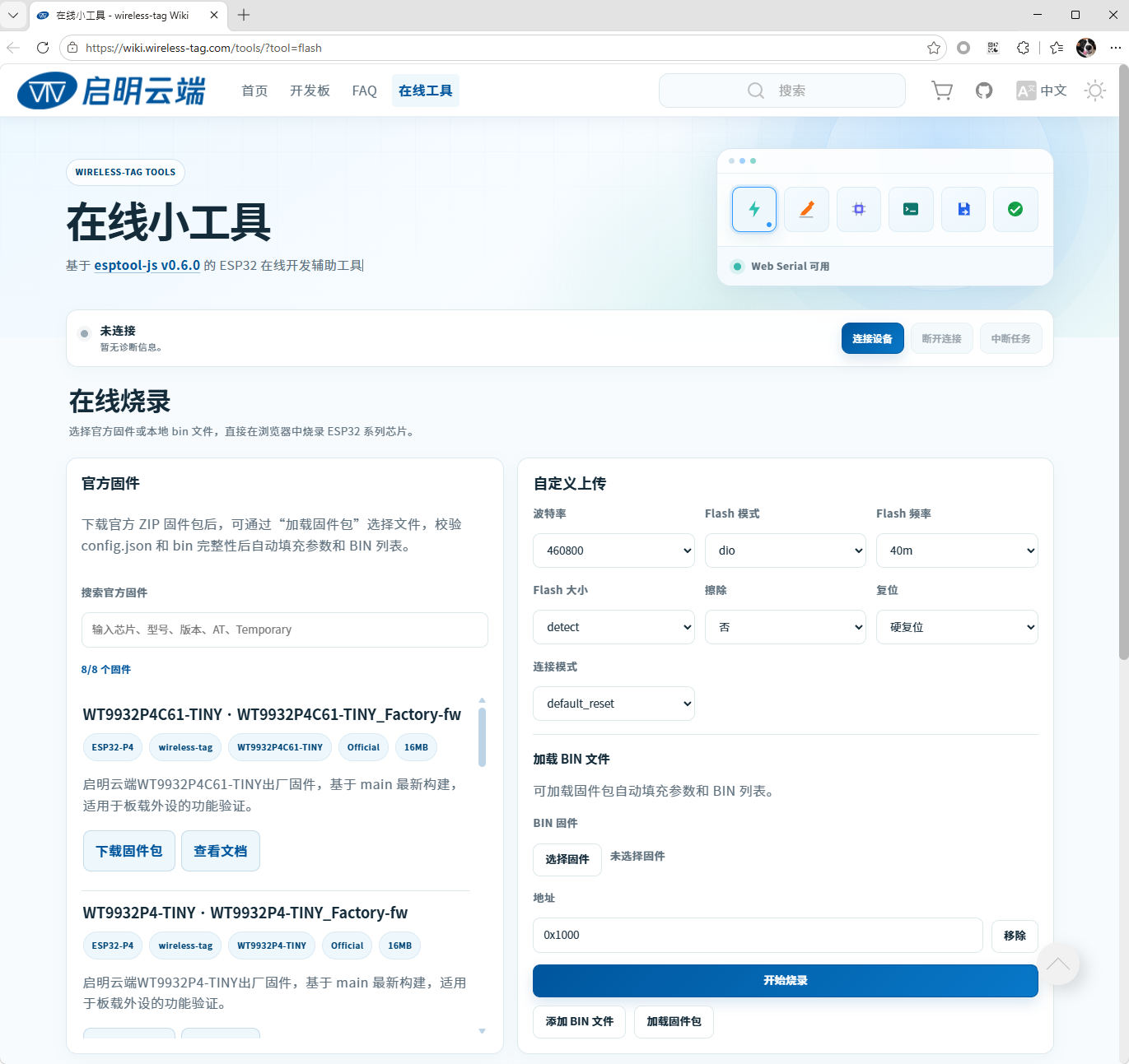
Open the Wireless-Tag online tools. The page appears as shown below:
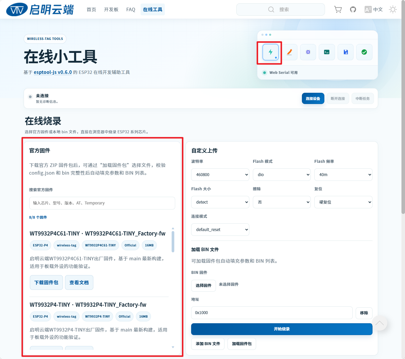
First, download the firmware package. Locate Online Flashing > Official Firmware in the area shown below:
Scroll through the highlighted area and select the package shown below. Check the firmware name carefully:
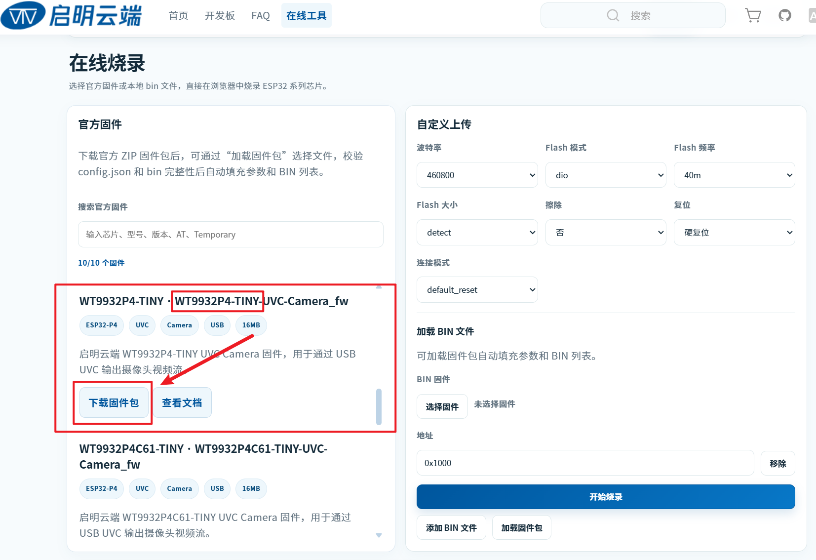
Click Download Firmware Package. The downloaded file is named WT9932P4-TINY-UVC-Camera_fw-online.zip.
Note: Do not extract the downloaded package. Load the ZIP file directly into the online flashing tool in the following steps.
Flashing Steps
Connect the Type-C end of a USB data cable to the
FUSBport and the other end to the computer. Open the online tool, then clickConnect Deviceas shown below:A device selection dialog appears after you click
Connect Device. The list may contain multiple devices. If you cannot identify the board's COM port, disconnect the other devices or unplug and reconnect this board to determine which COM port belongs to it.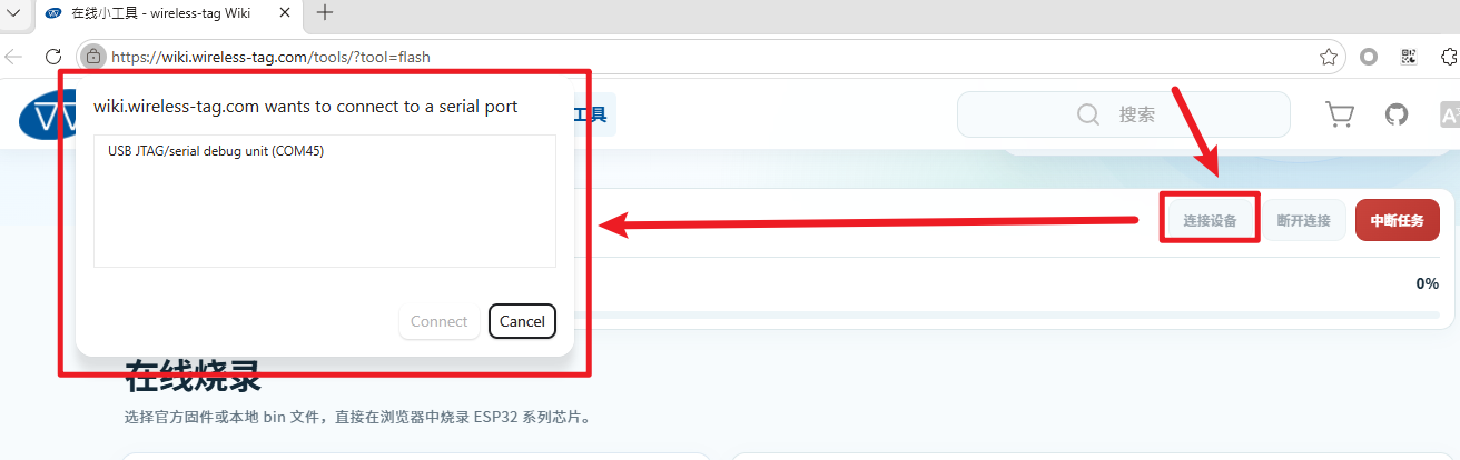
Select the device's COM port and click
Connect. Check the log area at the bottom of the page for the connection status. A successful connection is shown below: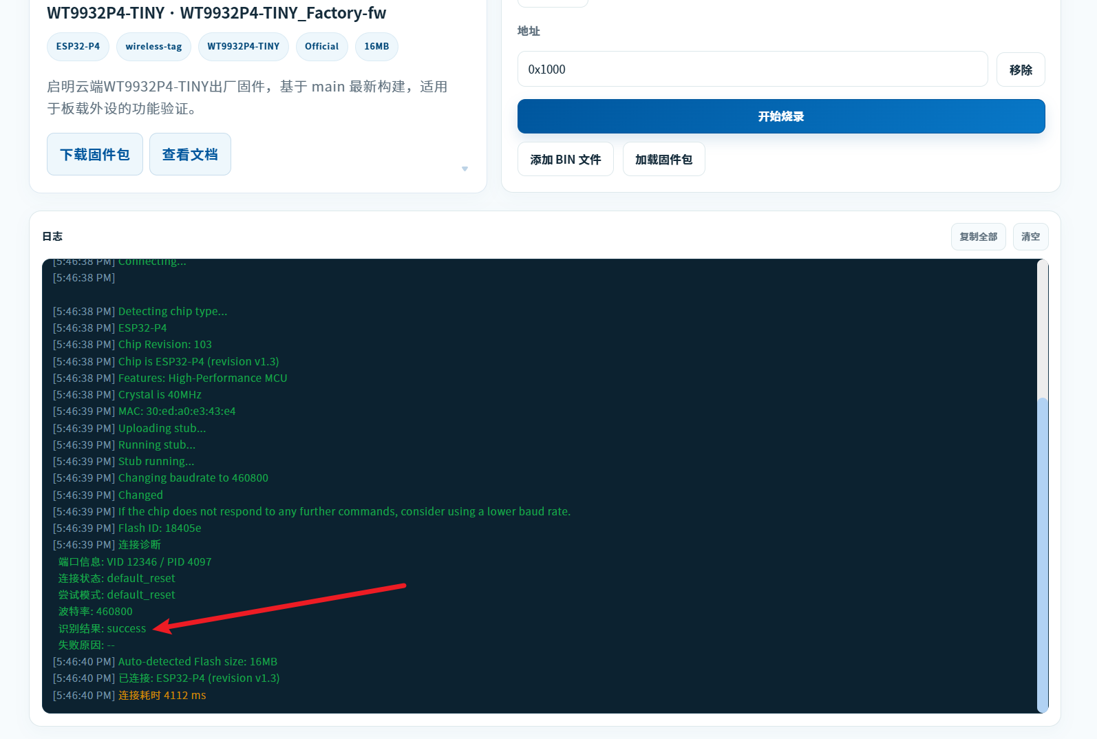
After the connection succeeds, click
Load Firmware Package. In the file dialog, select the previously downloaded WT9932P4-TINY-UVC-Camera_fw-online.zip package: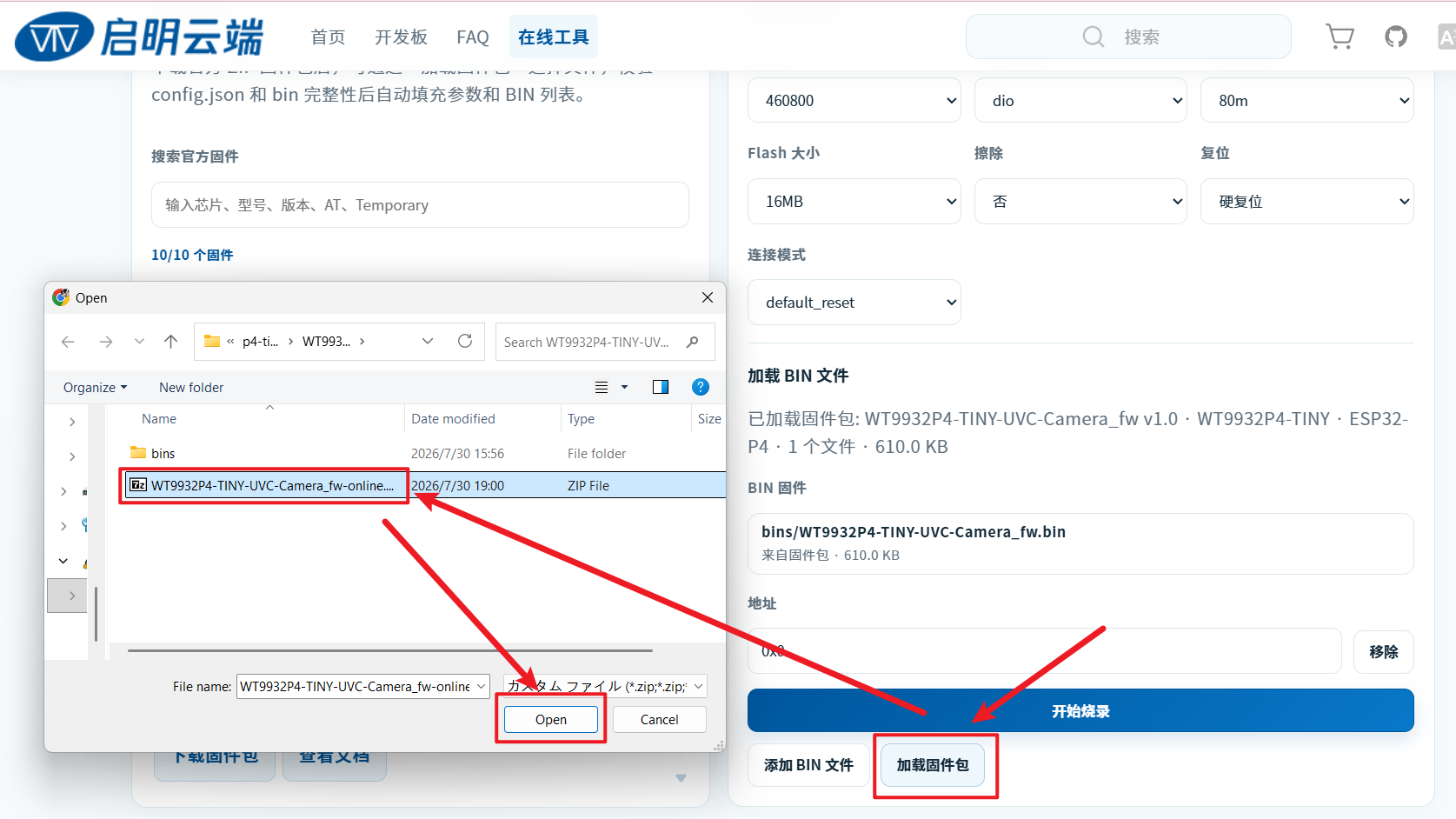
Click
Start Flashing. A confirmation dialog appears at the top of the page; clickOKto begin flashing: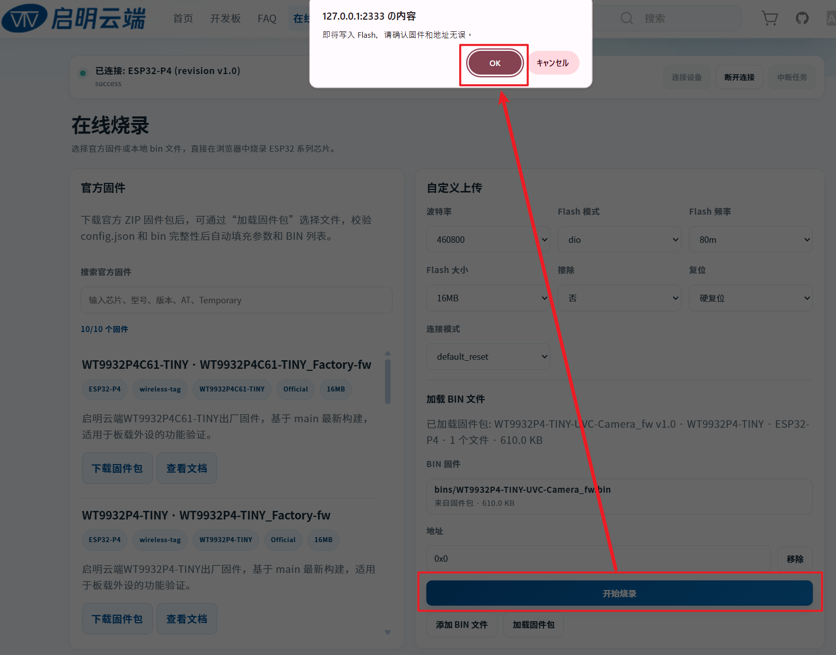
The following message indicates that flashing is complete:

The firmware has now been flashed. Disconnect the Type-C cable from the development board, then continue with the test procedure.
Test Procedure
After flashing the firmware as described above, disconnect the Type-C cable from the device.
Prepare all hardware required for the test:
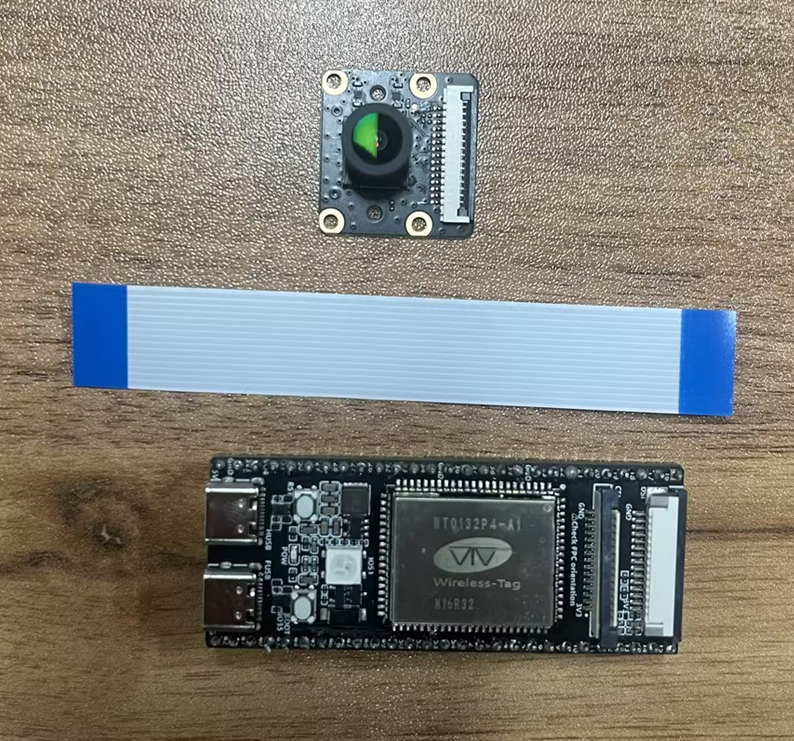
Connect the hardware as shown below:
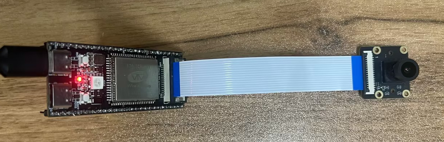
Connect one end of the USB Type-C cable to the PC and the other end to the HUSB port on the WT9932P4-TINY.
Expected behavior:
- The RGB LED remains off.
- The system detects a camera named
Wireless-Tag CSI Camera. Open a camera application on the PC to view the video stream. - Alternatively, on Windows 11, open Settings > Bluetooth & devices > Cameras, select
Wireless-Tag CSI Camera, and view the live preview shown below:
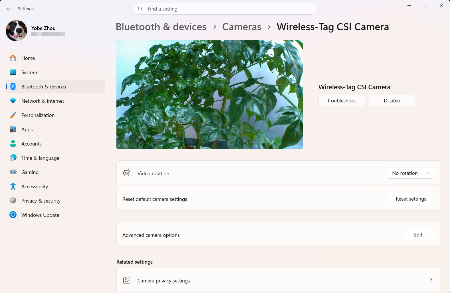
RGB LED Status
The RGB LED provides important status information:
| LED Color | Status |
|---|---|
| Red | Camera initialization failed; check the connections |
| Off | Operating normally |