English
WT99P4C5-S1 Flashing Guide
Update history
| Date | Version | Author | Update content |
|---|---|---|---|
| 2026-6-16 | 1.0.0 | Pail | First update of the document |
The WT99P4C5-S1 development board is shipped without pre-flashed firmware. You can start using it after flashing the firmware.
The WT99P4C5-S1 development board is designed with two modules: WT0132P4-A1 and ESP32-C5-WROOM-1, and they use different flashing methods.
WT0132P4-A1 Flashing Method
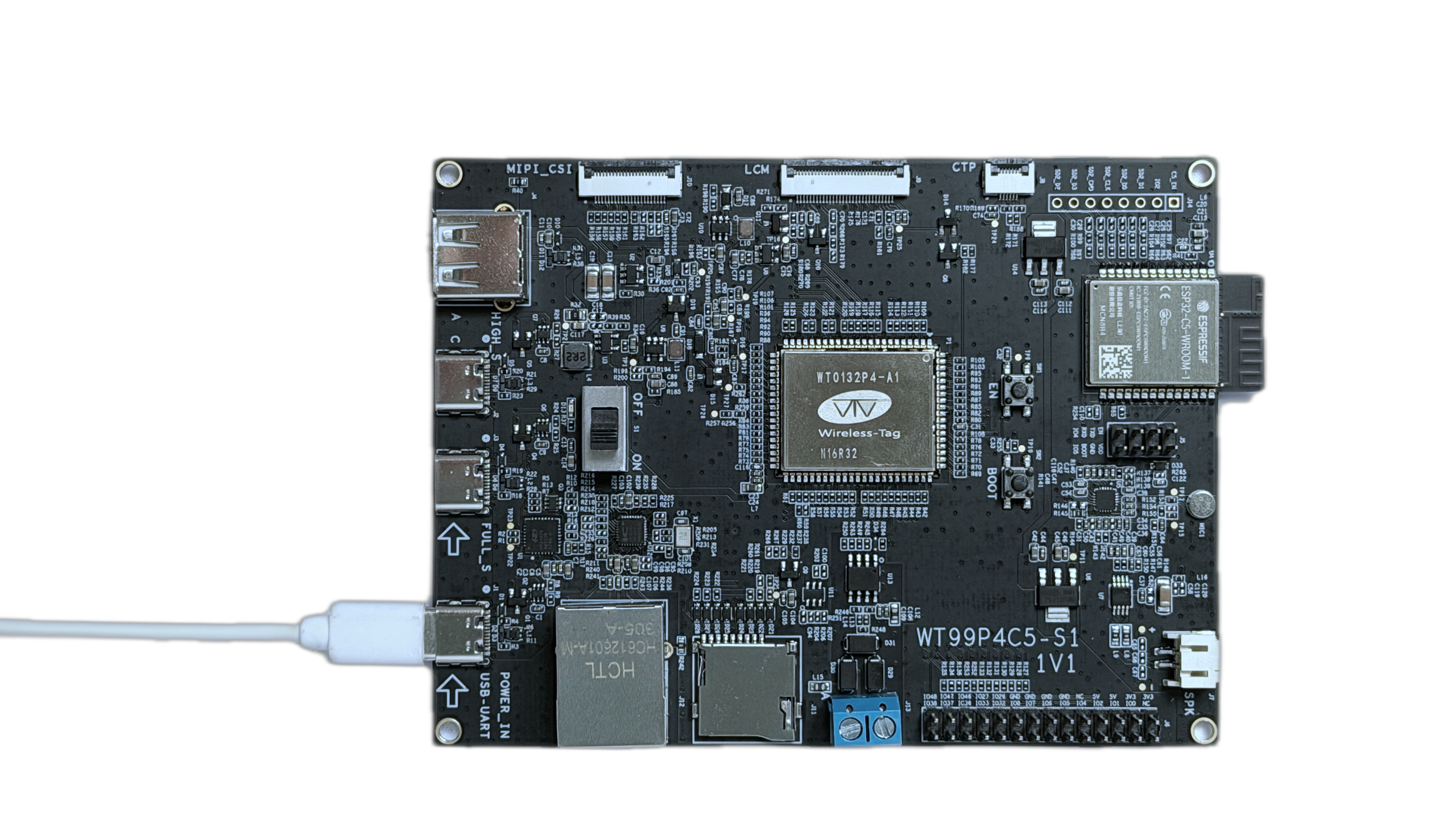
When using a USB Type-C data cable to connect the USB-UART interface at J1 on the development board to a computer (as shown below), press the Boot button, then briefly press the EN button, and then release the Boot button to enter the ESP32-P4 flashing download mode. At this point, you can use the ESP-TOOL host software to flash the firmware to the ESP32-P4 chip via the serial port.
WT0132P4-A1 Flashing Connection Diagram
ESP32-C5-WROOM-1 Flashing Method
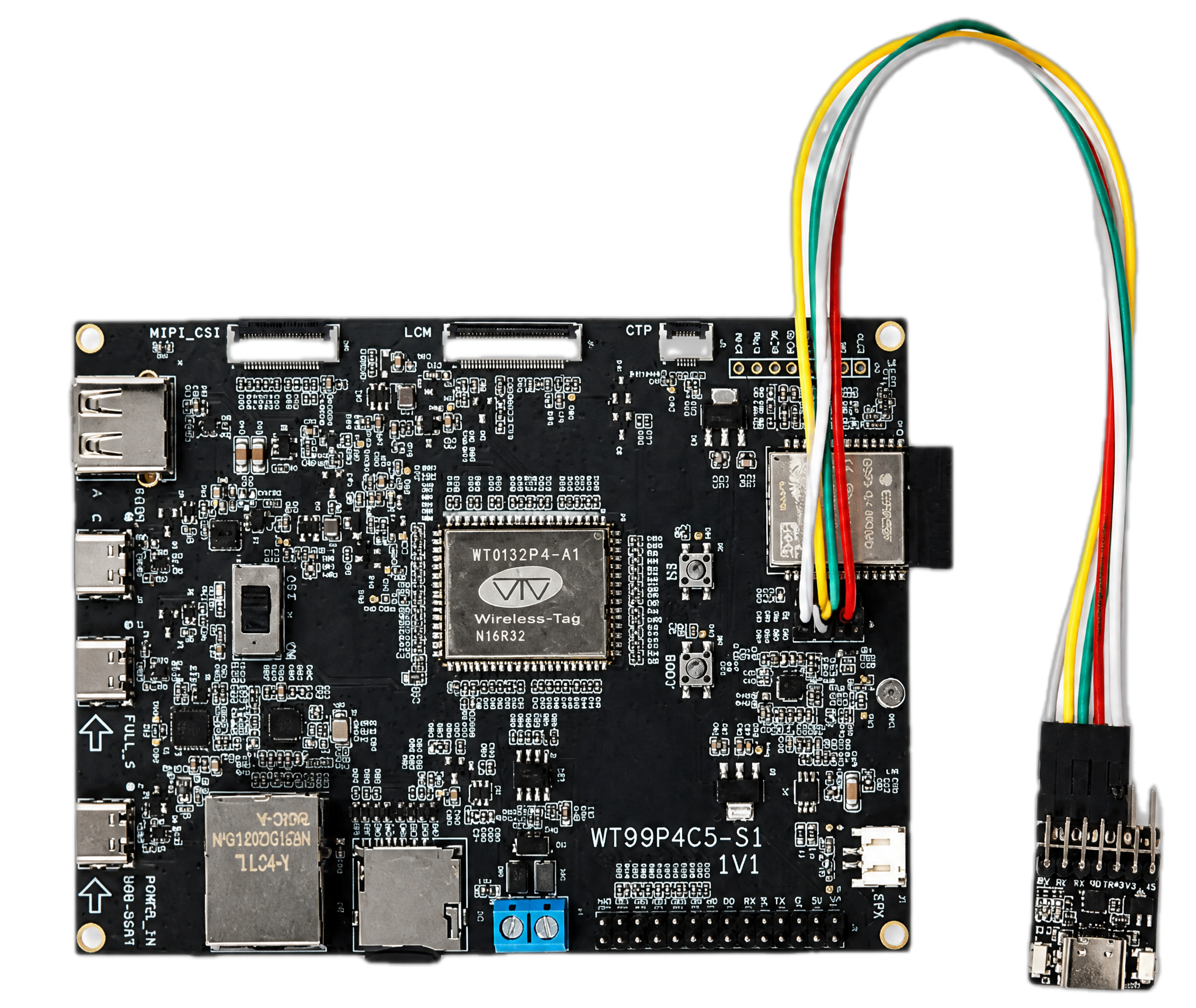
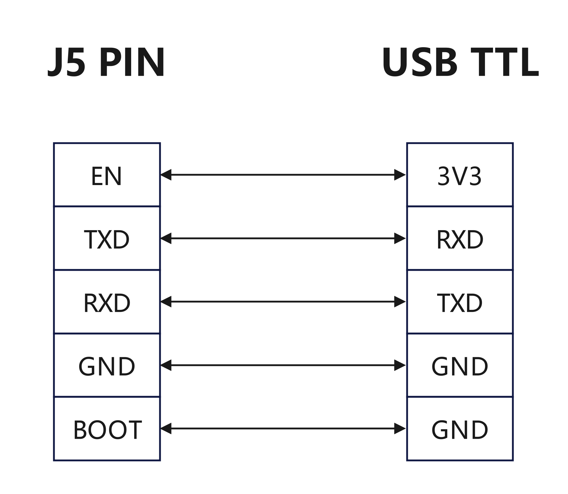
When using DuPont wires to connect the EN, TXD, RXD, GND, and BOOT pins at J5 of the development board to any serial flashing tool and then to a computer (as shown below), use a USB Type-C data cable to connect to any USB Type-C interface on the development board to power it. After powering on, the ESP32-C5 will enter the download mode. At this point, you can use the ESP-TOOL host software to flash the firmware to the ESP32-C5 chip via the serial port. (Note: To avoid SDIO communication between ESP32-P4 and ESP32-C5 affecting the flashing process, when flashing the ESP32-C5, you need to pull the EN of ESP32-P4 low.)
ESP32-C5-WROOM-1 Flashing Connection Diagram