English
WT9901C3-SN2 Feature Introduction
2026-05-12
Update history
| Date | Version | Author | Update content |
|---|---|---|---|
| 2026-05-12 | 1.0.1 | Yobie Zhou | Added board images |
| 2025-12-03 | 1.0.0 | Kirto | Initial document release |
1. Introduction
The WT9901C3-SN2 development board launched by Wireless-Tag is an embedded development board based on the WT32C3-S5 module, which is designed around the esp32c3 chipset. The core module, WT32C3-S5, supports both Wi-Fi and low-power Bluetooth (BLE) dual-mode communication, featuring a PCB onboard antenna and 2MB SPI Flash storage, making it ideal for IoT terminal device development.
In addition, this development board can also be used as a simple programmer. The pinout sequence is consistent with the Wireless-Tag programmer ESP-T02.
1.1 🔧 Core Hardware Configuration
- Communication Module: Onboard Wireless-Tag self-developed
WT32C3-S5module, integrated withWi-FiandBLEwireless communication protocols. It supports long-range, low-power, and high-connection capabilities, suitable for various IoT scenarios. - Pin Expansion: Most of the module's
GPIOpins are exposed to the side pin headers, making it easy for users to connect peripherals via jumper wires or directly insert the development board into a breadboard for rapid prototyping and debugging. - Hardware Flexibility: The development board is compact with abundant interfaces, making it suitable for building wireless sensor networks, remote data collection, industrial edge nodes, and other application scenarios.
1.2 🛠️ Design Features
- Onboard RGB LED: The board comes with an onboard
RGBLED, allowing users to customize their development. - Can be Used as a Programmer: By connecting
ENandGND, the development board can function as a programmer or serial monitor. - Breadboard Compatible: The pin spacing supports breadboard development, facilitating users in quickly setting up hardware environments.
- Cost-Effective: Offers great value for money, while supporting both
Wi-FiandBLEfeatures.
1.3 📡 Main Application Scenarios
- Smart Home: The module supports
ATcommands and can also be further developed. It is suitable as aWi-FiorBluetoothmodule for communication with the main controller in IoT smart home applications. It is a highly cost-effective development board. - Innovative Development & Education: With its rich interfaces (I2C/SPI/UART), it is ideal for university
IoTlab prototyping and development.
1.4 ⚙️ Development Advantages
- Supports
ATfirmware development, enabling users to quickly addWi-Fiand Bluetooth functionality to their existingMCUprojects. - Compatible with official
ESP-IDFdevelopment, offering users full control over peripherals and custom communication protocols. - Supports
Arduinodevelopment, making it easy and convenient for multi-module projects. - Supports
MicroPythondevelopment, with a lower entry barrier and no need for flashing.
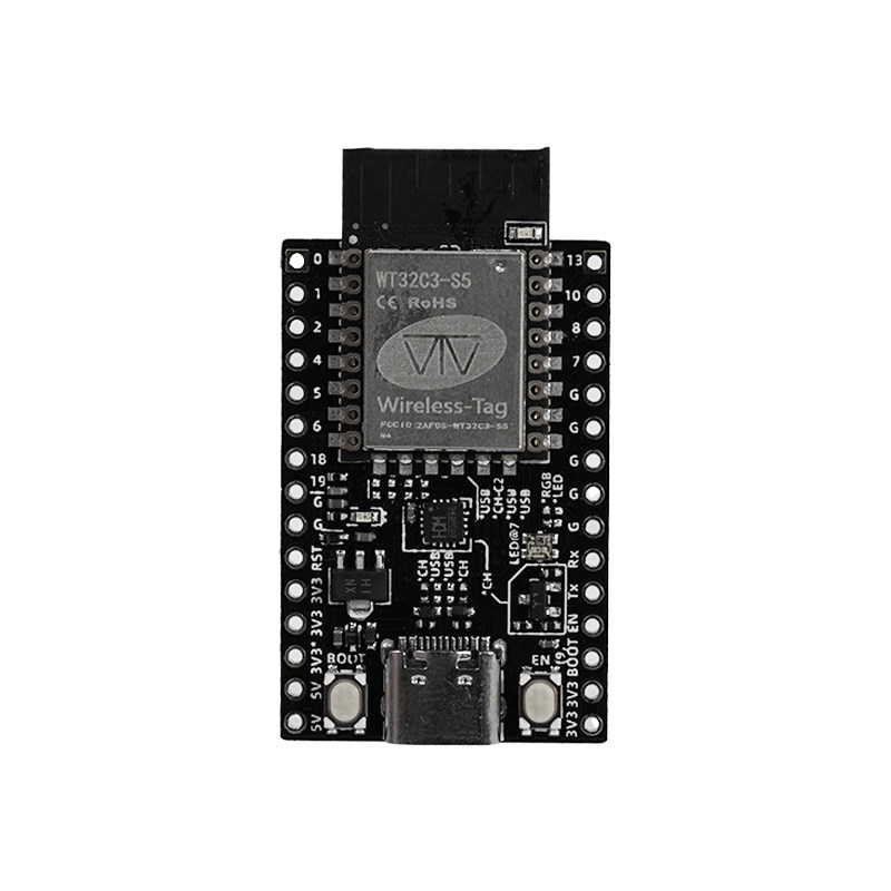
2. Pin Description
2.1 Left Pin Header
| Name | Function |
|---|---|
| IO0 | GPIO0 |
| IO1 | GPIO1 |
| IO2 | GPIO2 |
| IO4 | GPIO4 |
| IO5 | GPIO5 |
| IO6 | GPIO6 |
| IO18 | GPIO19 |
| IO19 | GPIO19 |
| GND | 3.3V Power |
| RST | 3.3V Power |
| VCC | 3.3V Power |
| VCC | 3.3V Power |
| VCC | 3.3V Power |
| 5V | 5V Power |
| 5V | 5V Power |
2.2 Right Pin Header
| Name | Function |
|---|---|
| IO3 | GPIO3 (silk screen incorrectly marked as 13) |
| IO10 | GPIO10 |
| IO8 | GPIO8, Blue LED on the module |
| IO7 | GPIO7, Green LED (C2: standard green LED, C3: WS2812 RGB) |
| GND | Ground |
| GND | Ground |
| GND | Ground |
| GND | Ground |
| GND | Ground |
| RX | U0TXD, GPIO20 (C3: GPIO21) Serial version: CH343_RX |
| TX | U0RXD, GPIO19 (C3: GPIO20) Serial version: CH343_TX |
| EN | Serial version: Connect to CH343_RST; USB version: Connect to module EN pin |
| BOOT | GPIO9 |
| VCC | 3.3V Power |
| VCC | 3.3V Power |
3. Power Supply Features
The WT9901C3-SN2 series development board can be powered using one of the following methods:
- External power supply via the
USB Type-Cport; - Connect the
VCCpower input pin using a Dupont wire to the corresponding voltage; - Connect the
5Vpower input pin using a Dupont wire to the corresponding voltage.