


 English
WT99P461-S1 Board Features
Update history
| Date | Version | Author | Update content |
|---|---|---|---|
| 2026-09-09 | 1.0.0 | Pail | Initial document release |
Introduction
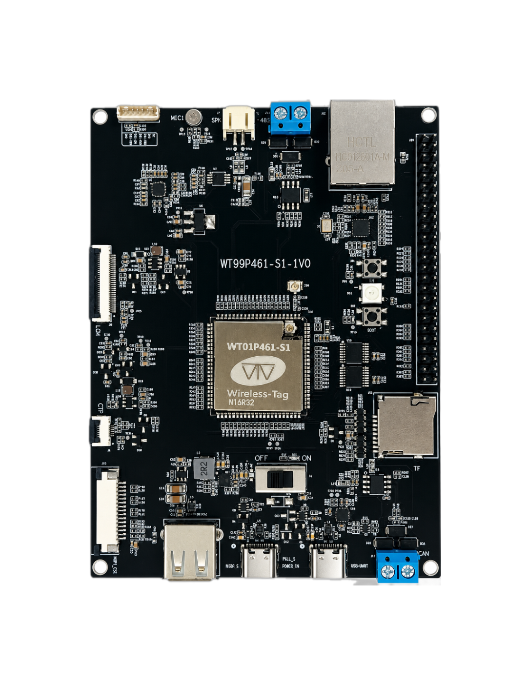
WT99P461-S1 is a high-performance multimedia development board from Shenzhen Wireless-tag Co., Ltd. It combines Espressif's ESP32-P4 chip (a dual-core RISC-V processor running at 400MHz) with an ESP32-C61 wireless chip on the WT01P461-S1 core board. With a comprehensive set of interfaces and multimedia processing capabilities, the board supports applications such as smart home control, industrial HMI, medical equipment, security monitoring, and multimedia terminals. Its performance, wireless connectivity, and integration make it suitable for rapid prototyping of IPC, AIoT, and similar products.
🔧 Core Hardware Configuration
Main Chips: The board uses Espressif's
ESP32-P4+ESP32-C61dual-chip architecture. TheESP32-P4features a dual-coreRISC-V 400MHzprocessor and32MB PSRAMfor multimedia processing and edge computing. TheESP32-C61provides2.4GHz Wi-Fi 6(802.11ax) andBluetooth 5.0 LE(withBluetooth Mesh 1.1support), enabling low-latency wireless connections with support for many concurrent devices.Network Interface: An integrated
RJ45Ethernet port supports10/100Mbpsauto-negotiation for direct wired networking. Together with theESP32-C61'sWi-Fi 6connectivity, it enables coordinated wired and wireless networking for redundancy and reliable data transmission in industrial applications.Multi-protocol Data Channels: The board supports seven communication interfaces:
serial (UART),Ethernet,Wi-Fi 6,Bluetooth,USB 2.0 OTG,RS-485, andCAN. Developers can use theESP-IDF SDKto implement data routing and protocol conversion between these interfaces, such asUART ↔ Ethernet passthrough, for custom industrial control applications.
🛠️ Design Features
- The
RS-485interface (J13) connects to anRS-485 PHYchip and complies with theTIA/EIA-485standard for industrial communication. - The onboard
RJ45Ethernet port (J12) supports10/100Mbpsauto-negotiation for Ethernet communication. - The
CANbus interface (J17) connects to aCAN PHYchip for industrial and automotive bus communication. - The full-speed
USB 2.0 Type-Cport (J3) connects to theESP32-P4'sUSB 2.0 OTG Full-Speedinterface. It can be used for development withESP-IDFand can also supply power to the board. - The high-speed
USB 2.0 Type-Aport (J4) connects to theESP32-P4'sUSB 2.0 OTG High-Speedinterface. TheESP32-P4can act as aUSB Hostto connect to and power otherUSB Deviceperipherals. - The
RGBLED (D41, connected to the core board throughGPIO54) can be used for custom status indications. - The
MicroSDcard slot (J11) supports4-bitmode for storing or playing audio files on aMicroSDcard. - The
MIPI CSI FPCconnector (J15,1.0mmpitch,15pins) connects to an external camera module for image transfer. - The
MIPI DSI FPCconnector (J9,0.5mmpitch,30pins) and theCTPconnector (J8,0.5mmpitch,6pins) connect to anLCDexpansion board. - The onboard microphone (
MIC1) and speaker connector (J7, supporting up to4Ω3.0W) connect to the onboard audio codec for voice announcements and audio playback. - The
C61-PROGflashing interface (J16,1.25mmpitch, single-row straight1x7Pheader) is used to flash theESP32-C61chip on theWT01P461-S1core board.
📡 Main Applications
- Industrial Control: The
RS-485andCANinterfaces connect toPLCs, sensors, and industrial equipment, whileEthernetand2.4GHz Wi-Fi 6provide stable and reliable network data transmission. - HMI:
MIPI-DSIandCTPsupport anLCDexpansion display with capacitive touch for developing local monitoring interfaces using embeddedGUIframeworks such asLVGL. - Security and Vision Terminals: The
MIPI-CSIcamera interface supports image capture, while theESP32-P4's400MHz RISC-Vcores support edgeAIinference, such as face recognition. - Smart Home Control Systems: The onboard audio codec supports voice announcements and local command recognition. Combined with the
HMI, it enables applications such as smart speakers with displays and home energy management controllers.
⚙️ Development Advantages
- Both the onboard
ESP32-P4andESP32-C61can be programmed using Espressif'sESP-IDFSDK. - Each chip has a dedicated flashing interface (
J16/J1), supporting serial flashing and debugging withESP-TOOL. - All available pins on the core board are brought out to headers, allowing developers to connect peripherals with jumper wires as needed.
- Official examples covering basic functions are available for learning and reference.
Pin Descriptions
The following tables list the names and functions of the development board's headers and pins (J20, J16, J13, and J17). Connector names correspond to the front view of the WT99P461-S1 development board, and pin numbers match the board schematic.
J20 Pin Functions
| Pin | Name | Function |
|---|---|---|
| 1 | VCC_3V3 | 3.3V power supply |
| 2 | C61_GPIO9 | GPIO9, ZCD1 |
| 3 | VCC_3V3 | 3.3V power supply |
| 4 | C61_GPIO8 | GPIO8, FSPICS0, ZCD0 |
| 5 | VCC_5V | 5V power supply |
| 6 | C61_GPIO7 | GPIO7, FSPID |
| 7 | VCC_5V | 5V power supply |
| 8 | C61_GPIO6 | GPIO6, LP_GPIO6, MTDO, FSPICLK |
| 9 | NC | Not connected |
| 10 | C61_GPIO5 | GPIO5, LP_GPIO5, MTCK, ADC1_CH3 |
| 11 | GND | Power ground |
| 12 | C61_GPIO4 | GPIO4, LP_GPIO4, MTDI, ADC1_CH2, FSPIWP |
| 13 | GND | Power ground |
| 14 | C61_GPIO1 | GPIO1, LP_GPIO1, XTAL_32K_N, ADC1_CH0 |
| 15 | GND | Power ground |
| 16 | C61_GPIO0 | GPIO0, LP_GPIO0, XTAL_32K_P |
| 17 | GND | Power ground |
| 18 | C61_EN | ESP32-C61 chip enable |
| 19 | GPIO1 | GPIO1, LP_GPIO1, XTAL_32K_P |
| 20 | C61_U0TXD | GPIO11, U0TXD |
| 21 | GPIO2 | GPIO2, MTCK, LP_GPIO2, TOUCH_CHANNEL1 |
| 22 | C61_U0RXD | GPIO10, U0RXD |
| 23 | GPIO3 | GPIO3, MTDI, LP_GPIO3, TOUCH_CHANNEL2 |
| 24 | NC | Not connected |
| 25 | GPIO4 | GPIO4, MTMS, LP_GPIO4, TOUCH_CHANNEL3 |
| 26 | GPIO5 | GPIO5, MTDO, LP_GPIO5, TOUCH_CHANNEL4 |
| 27 | GPIO6 | GPIO6, SPI2_HOLD_PAD, LP_GPIO6, TOUCH_CHANNEL5 |
| 28 | GPIO21 | GPIO21, ADC1_CHANNEL5 |
| 29 | GPIO22 | GPIO22, ADC1_CHANNEL6 |
| 30 | GPIO23 | GPIO23, ADC1_CHANNEL7, REF_50M_CLK_PAD |
| 31 | GPIO0 | GPIO0, LP_GPIO0, XTAL_32K_N |
| 32 | GPIO41 | GPIO41, SD1_CDATA2_PAD, GMAC_PHY_TXD0_PAD |
| 33 | GPIO53 | GPIO53, GMAC_PHY_RXD1_PAD, ADC2_CHANNEL4, ANA_COMP1 |
| 34 | GPIO42 | GPIO42, SD1_CDATA3_PAD, GMAC_PHY_TXD1_PAD |
| 35 | GPIO48 | GPIO48, SD1_CDATA7_PAD, GMAC_PHY_RXER_PAD |
| 36 | GPIO47 | GPIO47, SD1_CDATA6_PAD, GMAC_PHY_RXD1_PAD |
| 37 | GPIO40 | GPIO40, SD1_CDATA1_PAD, GMAC_PHY_TXEN_PAD |
| 38 | GPIO46 | GPIO46, SD1_CDATA5_PAD, GMAC_PHY_RXD0_PAD |
| 39 | GPIO39 | GPIO39, SD1_CDATA0_PAD, REF_50M_CLK_PAD |
| 40 | GPIO45 | GPIO45, SD1_CDATA4_PAD, GMAC_PHY_RXDV_PAD |
| 41 | GPIO38 | GPIO38, UART0_RXD_PAD, SPI2_DQS_PAD |
| 42 | GPIO36 | GPIO36, SPI2_IO6_PAD, GMAC_PHY_TXER_PAD |
| 43 | GPIO37 | GPIO37, UART0_TXD_PAD, SPI2_IO7_PAD |
| 44 | GPIO33 | GPIO33, SPI2_WP_PAD, GMAC_PHY_TXEN_PAD |
| 45 | GPIO43 | GPIO43, SD1_CCLK_PAD, GMAC_PHY_TXER_PAD |
| 46 | GPIO32 | GPIO32, SPI2_HOLD_PAD, GMAC_RMII_CLK_PAD |
| 47 | GPIO44 | GPIO44, SD1_CCMD_PAD, GMAC_RMII_CLK_PAD |
| 48 | GPIO27 | GPIO27, USB1P1_P1 |
| 49 | PWR_CTRL | Power control pin |
| 50 | GPIO26 | GPIO26, USB1P1_N1 |
J16 Pin Functions
| Pin | Name | Function |
|---|---|---|
| 1 | GND | Power ground |
| 2 | C61_GPIO9 | GPIO9, ZCD1 (10K pull-up inside the module) |
| 3 | C61_EN | ESP32-C61 chip enable (10K pull-up on the core board) |
| 4 | C61_U0RXD | GPIO10, U0RXD |
| 5 | C61_U0TXD | GPIO11, U0TXD |
| 6 | 3V3 | 3.3V power input |
| 7 | NC | Not connected |
J13 Pin Functions
| Pin | Name | Function |
|---|---|---|
| 1 | 485_B | Inverting receiver input and inverting driver output |
| 2 | 485_A | Non-inverting receiver input and non-inverting driver output |
J17 Pin Functions
| Pin | Name | Function |
|---|---|---|
| 1 | CAN_H | CAN bus high line |
| 2 | CAN_L | CAN bus low line |
Power Characteristics
Choose one of the following methods to power the WT99P461-S1 series development board:
- Supply power through the
J1(USB to UART)Type-Cdebugging port. - Supply power through the
J3(USB 2.0 Full-Speed)Type-Cport. - Connect a supply at the appropriate voltage to the
3V3or5Vpower input pins on theJ20header using Dupont wires.