English
WT9932C2-TINY Feature Introduction
Update history
| Date | Version | Author | Update content |
|---|---|---|---|
| 2026-05-12 | 1.0.1 | Yobie Zhou | Added board images and purchasing links |
| 2025-12-05 | 1.0.0 | Kirto | Initial document release |
1. Introduction
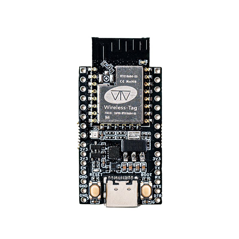
The TINY open-source development board series from wireless-tag includes the WT9932C2-TINY, an ultra-compact Wi-Fi + BLE development board based on Espressif’s ESP32-C2. It targets entry-level IoT applications, low-power wireless communication, and small-form-factor smart devices.
The ESP32-C2 is a cost-effective, low-power MCU featuring a single-core 32-bit RISC-V processor running up to 120 MHz, with integrated 2.4 GHz Wi-Fi and Bluetooth LE, and supports common peripherals including UART, SPI, I²C, PWM, ADC, etc., covering most lightweight embedded scenarios.
The chip includes an efficient low-power architecture, supporting Modem-sleep, Light-sleep, and provides essential security features such as secure boot and flash encryption. It is ideal for smart home appliances, small device controllers, sensor networks, and wearables where power, size, and cost are critical.
As a mini open-source development board, WT9932C2-TINY is designed to help developers quickly get started with ESP32-C2 by offering a low-cost, fully featured, and beginner-friendly wireless development platform, making Wi-Fi/BLE connectivity easy to integrate into any project.
Buy Now: WT9932C2-TINY Development Kit
1.1 🔧 Core Hardware Specifications
- Main MCU: ESP32-C2 (RISC-V, up to 120 MHz)
- Module: WT08684-S5 (integrated ESP32-C2)
- Wireless: 2.4 GHz Wi-Fi + Bluetooth LE
- USB-to-UART: On-board CH343P
- Buttons: RESET, BOOT (supports download mode)
- LED: 1 × WS2812 RGB LED (IO6)
- Power: LDO regulator, up to 1 A output
- Interfaces: Dual 15-pin ×2 headers (30 pins total), all GPIOs brought out
- Connectors: USB-C, 2.54 mm pin headers, breadboard-friendly
- Factory Firmware: MicroPython (boot into REPL instantly)
1.2 🛠️ Design Features
- Compact footprint (23 × 38 mm): Highly integrated, suited for space-constrained environments.
- Fully integrated development experience: On-board USB-to-UART, plug-and-play debugging (driver-free on most systems), RGB LED, buttons, power indicator, all pins exposed—ready for rapid prototyping with a breadboard.
- Can function as a USB-to-UART adapter: Short EN to GND → instantly becomes a USB-TTL tool.
- Stable power system: LDO output up to 1 A, suitable for external peripherals.
- Ready-to-use scripting environment: Ships with MicroPython, no flashing required.
1.3 📡 Typical Application Scenarios
- Compact smart home devices:
The module supports AT commands and custom firmware development. Ideal as a Wi-Fi/BLE communication module in smart home systems. Offers excellent cost-performance for embedded projects. - Innovation, education, and prototyping:
Rich interfaces (I2C/SPI/UART) make it suitable for IoT labs, coursework, and rapid prototyping. - Used as a USB-UART debugger:
Debug other MCUs or communication modules easily.
1.4 ⚙️ Development Advantages
- Plug-and-play with USB-C
- Built-in MicroPython—zero-threshold development
- Fully supported by official ESP-IDF for ESP32-C2
- All GPIOs exposed for sensors and external peripherals
- Dual-mode Wi-Fi + BLE simplifies IoT connectivity
- Can act as a USB-TTL adapter, improving tool reuse
- RGB LED for debugging/status indication—great for demos and teaching
- Small size and low cost—excellent for early-stage or production-prototype projects
2. Pin Description
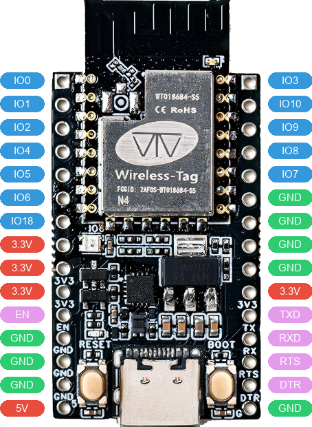
2.1 Left-Side Pins
| No. | Pin | Description | Voltage | Notes |
|---|---|---|---|---|
| 1 | IO0 | General Purpose I/O 0 | 0V/3.3V | |
| 2 | IO1 | General Purpose I/O 1 | 0V/3.3V | |
| 3 | IO2 | General Purpose I/O 2 | 0V/3.3V | |
| 4 | IO4 | General Purpose I/O 4 | 0V/3.3V | |
| 5 | IO5 | General Purpose I/O 5 | 0V/3.3V | |
| 6 | IO6 | General Purpose I/O 6 | 0V/3.3V | RGB LED |
| 7 | IO18 | General Purpose I/O 18 | 0V/3.3V | |
| 8 | 3.3V | Power Output | 3.3V | |
| 9 | 3.3V | Power Output | 3.3V | |
| 10 | 3.3V | Power Output | 3.3V | |
| 11 | EN | Reset pin | 0V | |
| 12 | GND | Ground | 0V | |
| 13 | GND | Ground | 0V | |
| 14 | GND | Ground | 0V | |
| 15 | 5V | Power Output | 5V |
2.2 Right-Side Pins
| No. | Pin | Description | Voltage | Notes |
|---|---|---|---|---|
| 1 | IO3 | General Purpose I/O 3 | 0V/3.3V | |
| 2 | IO10 | General Purpose I/O 10 | 0V/3.3V | |
| 3 | IO9 | General Purpose I/O 9 | 0V/3.3V | |
| 4 | IO8 | General Purpose I/O 8 | 0V/3.3V | |
| 5 | IO7 | General Purpose I/O 7 | 0V/3.3V | |
| 6 | GND | Ground | 0V | |
| 7 | GND | Ground | 0V | |
| 8 | GND | Ground | 0V | |
| 9 | GND | Ground | 0V | |
| 10 | 3.3V | Power Output | 3.3V | |
| 11 | RXD | CH343P UART Receive | 0V/3.3V | |
| 12 | TXD | CH343P UART Transmit | 0V/3.3V | |
| 13 | RTS | CH343P UART Flow Control (RTS) | 0V/3.3V | |
| 14 | DTR | CH343P UART Flow Control (DTR) | 0V/3.3V | |
| 15 | GND | Ground | 0V |
3. Power Characteristics
You can power the WT9932C2-TINY development board using any of the following methods:
- USB Type-C external power input
- Connect the appropriate voltage to the VCC pin using Dupont wires
- Connect the appropriate voltage to the 5V pin using Dupont wires