English
WT9932P4-MINI-A1 Feature Overview
Update history
| Date | Version | Author | Update content |
|---|---|---|---|
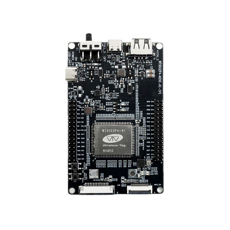
| 2026-05-12 | 1.0.1 | Yobie Zhou | Added board images and purchasing links |
| 2025-11-13 | 1.0.0 | Pail | First release |
1. Introduction
WT9932P4-MINI-A1 is a high-performance multimedia development board launched by Shenzhen Wireless-tag Co., Ltd. It is based on Espressif’s ESP32-P4 chip, featuring a dual-core RISC-V processor running at 400MHz. The core module model is WT0132P4-A1. This development board focuses on full-featured interfaces and multimedia processing capabilities. It is suitable for applications such as smart home control, industrial HMI, medical devices, security monitoring, and multimedia terminals. With low cost, low power consumption, and high integration, it is ideal for rapid prototyping of products like IPC and AIoT devices.
Buy Now: WT9932P4-MINI-A1 Development Kit
1.1 🔧 Core Hardware Specifications
Main Controller: Powered by the Espressif
ESP32-P4, featuring a high-performanceRISC-V 400MHzprocessor and multiple multimedia subsystems, including aJPEG codec,Pixel Processing Accelerator,H.264 video encoder, andMIPI interface.Network Interface: Equipped with a
MINI-PCIeinterface that supportsCAT1 modules,Sub-1G modules, orWi-Fi extension boardsfor wireless communication. It can also be paired with aPOEexpansion board (IEEE 802.3af) to provide wiredEthernetnetworking (10/100Mbpsadaptive) andPOE power supply(48V input), ensuring reliable networking and power stability in industrial environments.Multimedia Interfaces: Natively supports both
MIPI-CSIandMIPI-DSIinterfaces.MIPI-CSIconnects to MIPI camera modules and supports2-lane x 1.5 Gbps.MIPI-DSIconnects to MIPI display panels and supports2-lane x 1.5 Gbps.
Developers can freely choose peripherals compatible with the onboard MIPI connectors.
1.2 🛠️ Design Features
- High-speed
USB 2.0 Type-C/Type-Ainterface, programmable viaESP-IDF. - Onboard power indicator and physical power switch for convenient power control.
MIPI-CSI FPCconnector (0.5mm pitch, 22 pins) for external camera modules.MIPI-DSI FPCconnector (1.0mm pitch, 15 pins) for LCD expansion boards.MINI-PCIeconnector (0.8mm pitch, 52 pins), wired to the core module’sUARTandDM/DPsignals, allowing external communication modules or expansion boards for wireless data transmission.
1.3 📡 Primary Application Scenarios
Data Acquisition: Features 45 general-purpose
GPIOsthat can be mapped toSPI,I2C,I2S, etc. Includes built-inADC/DACandtemperature sensing system, enabling easy integration with various sensors.Industrial Control: With
Wi-Fi&Sub-1Gexpansion boards, it can support long-range Sub-1G communication and cloud connectivity via Wi-Fi, suitable for industrial gateway applications.HMI Interfaces: Supports up to 7-inch (and smaller)
MIPIorRGBdisplays plus capacitive touch, ideal for localized monitoring interfaces based on frameworks likeLVGL.Security & Vision Terminals: With
MIPI-CSI/DVP/USBcamera interfaces supporting1080P@30fpsimage capture, combined with the400MHz RISC-Vcore and ESP-WHO algorithms, it enables edge AI inference such as facial recognition.
1.4 ⚙️ Development Advantages
- The
ESP32-P4can be developed using Espressif’sESP-IDFSDK. - Official example projects are provided for learning and reference.
- Multiple
MIPI-DSIandMIPI-CSIexamples are available on Qiming Cloud’s GitHub, ready to download and flash.
2. Pin Description
The table below lists the pin names and functions for the J5 header.
| Name | Function |
|---|---|
| IO33 | GPIO33, I3CMST_SDA, GPSPI SPI2 WP, EMAC PHY TXEN, DBG_PSRAM_DQ5 |
| IO26 | GPIO26, USB1P1_N1 |
| IO32 | GPIO32, I3CMST_SCL, GPSPI SPI2 HOLD, EMAC RMII CLK, DBG_PSRAM_DQ4 |
| IO27 | GPIO27, USB1P1_P1 |
| IO35 | GPIO35, GPSPI SPI2 IO5, EMAC PHY TXD1, DBG_PSRAM_DQ7 |
| IO37 | GPIO37, UART0_TXD, GPSPI SPI2 IO7 |
| VO4 | Power Output (0.5~2.7V or 3.3V, max 0.2A) |
| IO38 | GPIO38, UART0_RXD, GPSPI SPI2 DQS |
| IO48 | GPIO48, SD1_CDATA7_PAD, GMAC_PHY_RXER_PAD |
| IO39 | GPIO39, SD1_CDATA0_PAD, REF_50M_CLK_PAD |
| IO47 | GPIO47, SD1_CDATA6_PAD, GMAC_PHY_RXD1_PAD |
| IO40 | GPIO40, SD1_CDATA1_PAD, GMAC_PHY_TXEN_PAD |
| IO46 | GPIO46, SD1_CDATA5_PAD, GMAC_PHY_RXD0_PAD |
| IO41 | GPIO41, SD1_CDATA2_PAD, GMAC_PHY_TXD0_PAD |
| IO45 | GPIO45, SD1_CDATA4_PAD, GMAC_PHY_RXDV_PAD |
| IO42 | GPIO42, SD1_CDATA3_PAD, GMAC_PHY_TXD1_PAD |
| IO53 | GPIO53, GMAC_PHY_RXD1_PAD, ADC2_CHANNEL6, ANA_COMP1 |
| IO43 | GPIO43, SD1_CCLK_PAD, GMAC_PHY_TXER_PAD |
| IO54 | GPIO54, GMAC_PHY_RXER_PAD, ADC2_CHANNEL7, ANA_COMP1 |
| IO44 | GPIO44, SD1_CCMD_PAD, GMAC_RMII_CLK_PAD |
| IO31 | GPIO31, GPSPI SPI2 Q, EMAC PHY RXER, DBG_PSRAM_HOLD |
| IO30 | GPIO30, GPSPI SPI2 CK, EMAC PHY RXD1, DBG_PSRAM_WP |
| IO49 | GPIO49, GMAC_PHY_TXEN_PAD, ADC2_CHANNEL2 |
| IO29 | GPIO29, GPSPI SPI2 D, EMAC PHY RXD0, DBG_PSRAM_Q |
| IO50 | GPIO50, GMAC_RMII_CLK_PAD, ADC2_CHANNEL3 |
| IO28 | GPIO28, GPSPI SPI2 CS, EMAC PHY RXDV, DBG_PSRAM_D |
| IO51 | GPIO51, GMAC_PHY_RXDV_PAD, ADC2_CHANNEL4, ANA_COMP0 |
| IO34 | GPIO34, GPSPI SPI2 IO4, EMAC PHY TXD0, DBG_PSRAM_DQ6 |
| IO52 | GPIO52, GMAC_PHY_RXD0_PAD, ADC2_CHANNEL5, ANA_COMP0 |
| IO35 | GPIO35, GPSPI SPI2 IO5, EMAC PHY TXD1, DBG_PSRAM_DQ7 |
The table below lists the pin names and functions for the J6 header.
| Name | Function |
|---|---|
| 3V3 | 3.3V power output |
| IO23 | GPIO23, ADC1_CHANNEL7, REF_50M_CLK_PAD |
| 3V3 | 3.3V power output |
| IO22 | GPIO22, ADC1_CHANNEL6 |
| 3V3 | 3.3V power output |
| IO21 | GPIO21, ADC1_CHANNEL5 |
| IO20 | GPIO20, ADC1_CHANNEL4 |
| GND | Ground |
| IO19 | GPIO19, ADC1_CHANNEL3 |
| GND | Ground |
| IO18 | GPIO18, ADC1_CHANNEL2 |
| GND | Ground |
| IO17 | GPIO17, ADC1_CHANNEL1 |
| GND | Ground |
| VCC_5V | 5V power output |
| EN | GPIO16, ADC1_CHANNEL0 |
| IO1 | GPIO1, LP_GPIO1, XTAL_32K_P |
| IO15 | GPIO15, LP_GPIO15, LP_UART_RXD_PAD, TOUCH_CHANNEL13 |
| IO0 | GPIO0, LP_GPIO0, XTAL_32K_N |
| IO14 | GPIO14, LP_GPIO14, LP_UART_TXD_PAD, TOUCH_CHANNEL12 |
| IO9 | GPIO9, UART0_CTS_PAD, SPI2_CK_PAD, LP_GPIO9, TOUCH_CHANNEL7 |
| GND | Ground |
| IO6 | GPIO6, SPI2_HOLD_PAD, LP_GPIO6, TOUCH_CHANNEL4 |
| GND | Ground |
| VIN_5V | 5V power input |
| IO13 | GPIO13, UART1_CTS_PAD, LP_GPIO13, TOUCH_CHANNEL11 |
| VIN_5V | 5V power input |
| IO12 | GPIO12, UART1_RTS_PAD, LP_GPIO12, TOUCH_CHANNEL10 |
3. Power Specifications
The WT9932P4-MINI-A1 development board can be powered using any of the following methods:
- External power via the
Type-Cdebugging interface - External power via the
USB Type-Cinterface - Using the
VIN_5Vpower input with DuPont wires at the appropriate voltage